SmartCom
2
Control Installation and User Manual
6
SmartCom
2
Control Installation and User Manual
7
2.2 General Wiring Specifi cations
Connect as shown below.
Note: The recommended minimum mounting height
only applies when the internal sensor is used.
Ensure that the controller is
installed no less than 1.5m
above the fl oor level.
The controller can be
positioned with the cable
entry to the bottom or the
top depending on the cable
routing.
The lid with display and
connecting ribbon cable
can be rotated through 180
degrees to accommodate
top or bottom cable entry.
Do not mount the controller
on a warm surface or where
it could be affected by
direct sunlight or other heat
sources.
The mounting surface
should be non-conducting
or earth bonded and should
prevent access to the rear of
the control.
●
●
●
●
●
Figure - Minimum height
above fl oor level.
A drilling
template is
provided to
enable the
controller
assembly to
be securely
fi xed to a
solid
surface.
●
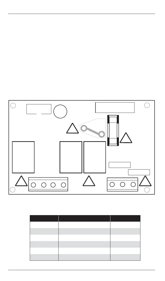
2.3 LITE VERSION WIRING CONNECTIONS
Terminal No: Connection Capacity mm
2
9 Burner Reset output 2.5
6 Heat 1 relay output 2.5
40 Vent 1 relay output 2.5
1 Live supply input 2.5
2Neutral supply input2.5
10 Flame failure input 2.5
Figure - Lite version PCB connections
9 6 40 1 2 10
FUSE
NEUT
LIVE
!
!
!
!
!
Figure - Controller
mounting holes
All wiring connections must be made by a suitably qualifi ed person.
Please refer to the following wiring connection drawings (2.3 to 2.6) and observe
the note at the bottom of each page referring to cable type and length. Failure
to follow these guidelines may result in electrical interference or unsatisfactory
operation. When making connections to screw terminals please ensure that no
more than 6mm of insulation is stripped back and that no stray wire strands escape.
The Ambi-Rad group of companies produces a wide range of product types. With
each product despatched, there are specifi c wiring instructions showing how to
connect the controls detailed in these instructions, to the product. It is important
to read both the product instructions and these control instructions to ensure
satisfactory operation.
 Loading...