SmartCom
2
Control Installation and User Manual
20
SmartCom
2
Control Installation and User Manual
21
Figure – Entering the Engineer function PIN code
Press the + or – buttons until the correct fi rst digit of the PIN code is displayed. Press
OK to enter this digit.
Once accepted the second zero will fl ash. Press the + or – buttons until the correct
second digit of the PIN code is displayed. Press OK to enter this digit.
The third zero will fl ash. Press the + or – buttons until the correct third digit of the
PIN code is displayed. Press OK to enter this digit.
Next the fourth zero will fl ash. Press the + or – buttons until the correct fourth digit
of the PIN code is displayed. Press OK to enter this digit.
Once the PIN code has been set and accepted, you will immediately gain access to
the control settings (explained below).
Access will remain available for 60 seconds after the last button press, after which
the PIN code will have to be entered again to get access to the settings.
If the PIN code is not available, contact the manufacturer for the master PIN code.
●
●
4.1 General Password (PIN Protection)
When the ENGINEER function is invoked, the controller will prompt you for the
password; the [PIN] icon will be displayed and four zeros will be displayed with the
fi rst zero fl ashing.
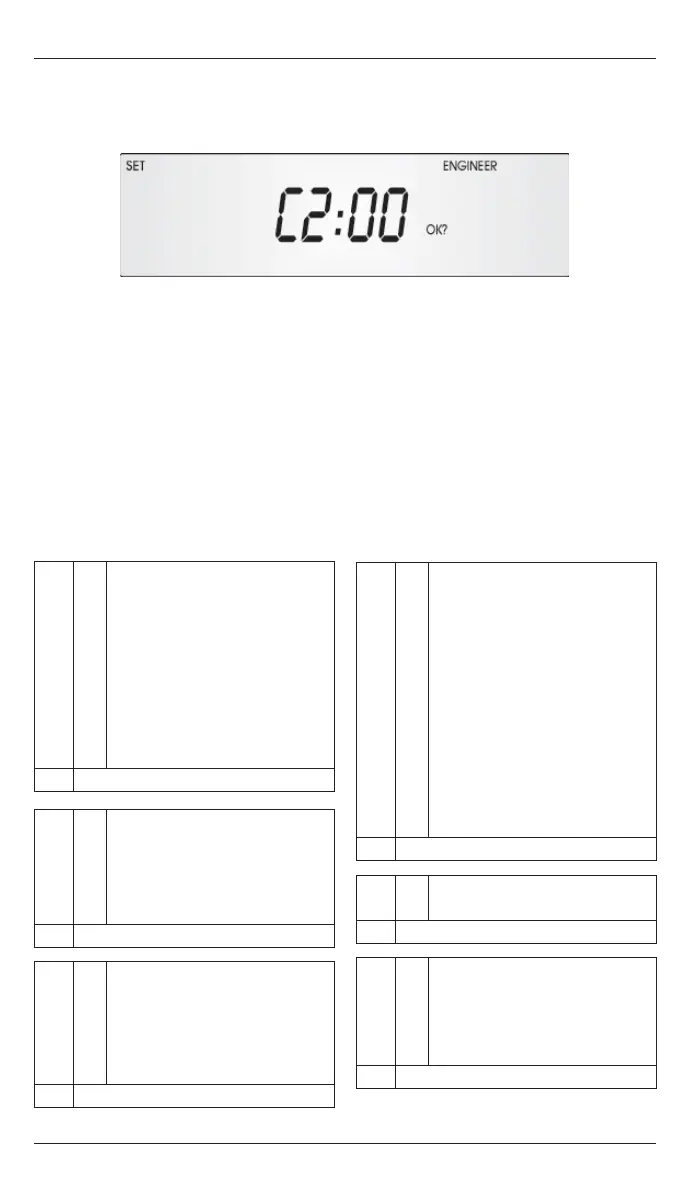
Figure - Engineer variable
Press the SETTINGS button until the desired variable code is displayed.
Press the OK button to accept this variable. The variable value (second two digits)
will start fl ashing.
Press the + or – buttons until the desired variable value is displayed.
Press OK to accept this value. The variable value will stop fl ashing.
Press the SETTINGS button to advance to another variable code.
4 ENGINEER FUNCTIONS
The engineer functions allow you to program various advanced parameters.
Depending on the version of the controller (i.e. Lite, Standard, Advanced or
Network), some options may not be available although displayed.
In order to access the engineer functions press and hold the + button and press the
SETTINGS button. The [SET] and [ENGINEER] icons are displayed.
All control functions may be optionally password protected by a PIN code (see
section 4.1).
Pressing the UNDO button during programming will cause the setting being
programmed to be changed back to its original value.
Pressing the UNDO button twice, consecutively, at any time while in the engineer
function, will cause the controller to exit the engineer function and return to
normal operation. Only items which have been OK’d will be changed.
If no keypad action takes place for 60 seconds while in the engineer function, the
controller will exit the engineer function and return to normal operation. Only
items which have been OK’d will be changed.
The engineer settings cannot be programmed over the communications link. The
engineer settings can only be programmed on the specifi c controller.
●
●
●
●
●
●
●
●
4.2 Programming The Engineer Functions
All engineer functions are displayed as a code in the fi rst two digits of the display,
e.g. C1, t1, t2, and a variable in the second two digits.
Control method.
A1: 0 Warm air control, vent 1 is
a fan.
1 Warm air control, vent 1 is a
damper.
2 Radiant / NorRayVac /
Herringbone standard
control.
3 Niche / Nordair control.
4 Radiant / NorRayVac /
Herringbone Multi-Zone /
Spilt-Zone operation.
Default value = 0
A2: 0 Frost Protection and Night
Setback enabled.
1 Frost Protection disabled,
Night Setback enabled.
2 Frost Protection and Night
Protection disabled.
Default value = 0
A3: 0 Lockout reset is Warm Air
mode (Heat and Time relays
are active during reset).
1 Lockout reset is Radiant
mode (Heat and Time relays
are off for 10s before and
during reset).
Default value = 0
A4: 0 Input B2 is multiple function.
1 Input B2 is Remote Frost/
Door Interlock input.
2 Input B2 is Blocked Filter
warning, enabled by Heat
relay.
3 Input B2 is Air Flow Failure
lockout, enabled by Heat
relay.
4 Input B2 is Blocked Filter
warning, enabled by Time
relay.
5 Input B2 is Air Flow Failure
lockout, enabled by Time
relay.
Default value = 1
A5: 0 Exam mode disabled.
1 Exam mode enabled.
Default value = 0
A6: 0 Slave control does not
respond to remote off
command from master.
1 Slave control does respond
to remote off command from
master.
Default value = 1
4.3 The Engineer Variables
NB Certain of the following options should be ignored if they are not relevant to
the control version being confi gured.
 Loading...