SmartCom
2
Control Installation and User Manual
4
SmartCom
2
Control Installation and User Manual
5
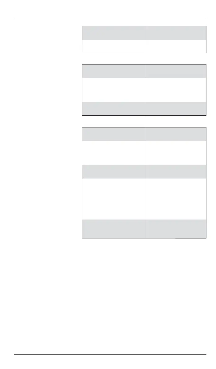
1.3 Lite Version Electrical
Specifi cations
Burner reset, Heat and
Vent 1 relay rating:
7A/240Vac resistive
2A/240Vac inductive
Control power
consumption:
3W
1.4 Standard
Version Electrical
Specifi cations
The power supply is non-
isolated, therefore all wiring
to the control must be mains
level rated.
Burner reset, Heat and
Std Vent 1 relay rating:
7A/240Vac resistive
2A/240Vac inductive
550W Vent 1 relay rating:
10A/240Vac resistive
3A/240Vac inductive,
(550W single phase
motor, max)
Control power
consumption:
3W
1.5 Advanced
and Network
Version Electrical
Specifi cations
The power supply is SELV
isolated, therefore low
voltage wiring to the control
does not need to be mains
level rated.
All relays except Vent 1
rating:
10A/240Vac resistive
2A/240Vac inductive
Vent 1 relay rating:
10A/240Vac resistive
3A/240Vac inductive,
(550W single phase
motor, max)
Control power
consumption:
5W
Communications wiring:
Screened twisted pair
Daisy-chain
confi guration.
Belden 9841 cable
recommended.
Maximum cable length
= 500m
0 – 10V signals
Output impedance = 500
Ohm. Max current drive
capacity = 5mA
2 INSTALLATION INSTRUCTIONS
2.1 Mounting the Control Assembly
The housing consists of a two
part plastic moulding held
together by four screws.
Plugs are supplied to cover
the screws following
installation.
Figure - Controller assembly
Remove the screws.
Carefully lift the lid and unplug the
ribbon cable from the power PCB
assembly situated in the bottom of
the case.
●
●
Note:
Knockouts are provided for cable
glands to allow mains and control
cables to be fi tted to the control
assembly. Knock the plastic out to
fi t the glands as required. Never
leave holes that allow fi nger access.
 Loading...