SmartCom
2
Control Installation and User Manual
8
SmartCom
2
Control Installation and User Manual
9
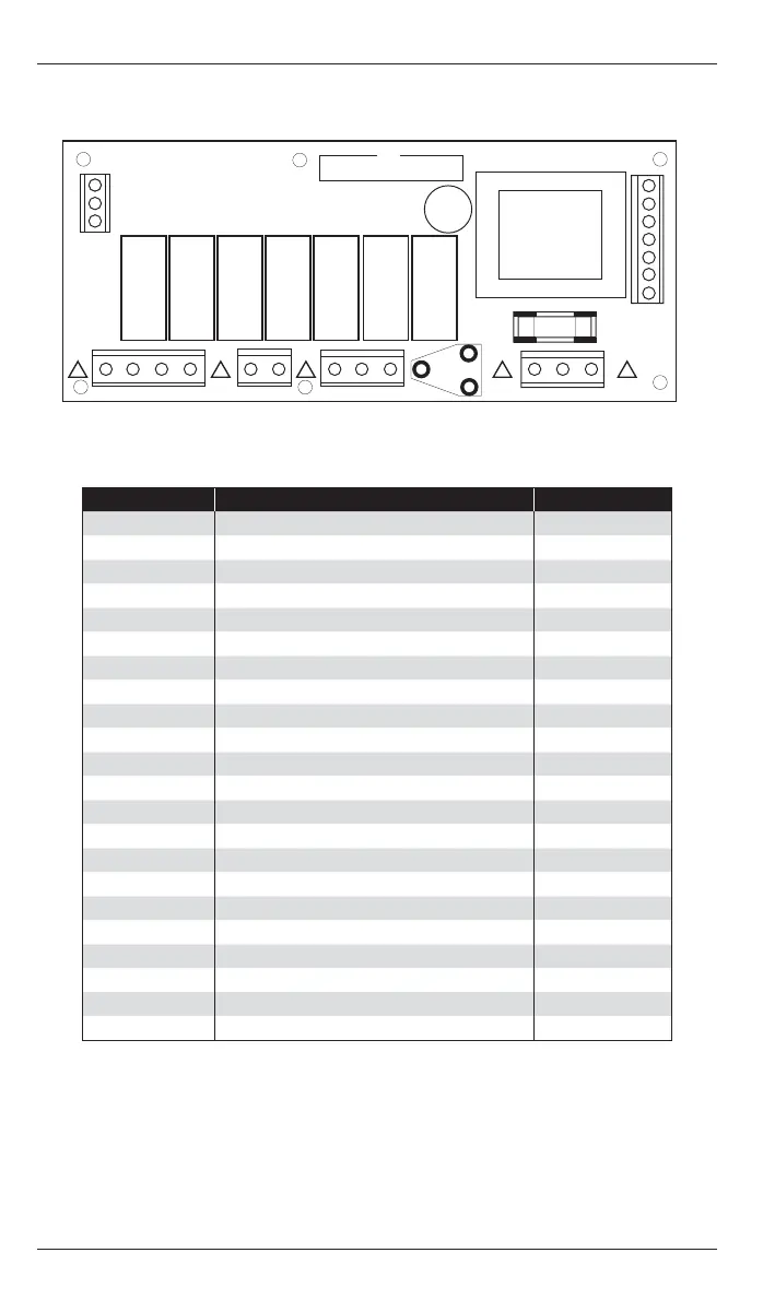
2.5 ADVANCED VERSION WIRING CONNECTIONS
Figure - Advanced version PCB connections
2.4 STANDARD VERSION WIRING CONNECTIONS
Terminal No: Connection Capacity mm
2
9 Burner Reset output 2.5
5Time relay output 2.5
6 Heat 1 relay output 2.5
40 Vent 1 relay output 2.5
41
Vent 1 relay input (550W relay
version only)
2.5
1Live supply input 2.5
2Neutral supply input 2.5
10 Flame failure input 2.5
S/R0 Remote room temperature sensor ‘A’ 1.5
S/R1 Remote room temperature sensor ‘B’ 1.5
B1 Remote On input (BMS ON INPUT) 1.5
B0 Remote common (Output to BMS) 1.5
B2 Remote input (see 4.4) 1.5
Figure - Standard version PCB connections
B2
B0
B1
9 564041 1210
FUSE
NEUT
LIVE
S/R0
S/R1
!
!
!
!
LIVE
FUSE
NEUT
B2
B0
B1
D1
D0
S/R1
S/R0
66
64
20
! ! !
41 40
7
8
9
25 14
5
6 1/L
2/N
10
! !
A terminal block is supplied to enable multiple connections to BO/B2 as detailed in product
wiring connections.
0-10V outputs and remote switch inputs should be connected by 0.75mm
2
cable of maximum
length 100m.
The remote temperature sensor may be placed at a distance of up to 100m (maximum) from
the control unit, using screened 0.75mm
2
cable. Connect the screen to terminal B0.
All sensor and signal wiring should be kept separate from mains wiring to minimise noise
pick-up.
A terminal block is supplied to enable multiple connections to BO/B2 as detailed in product
wiring connections.
Remote switch inputs should be connected by 6A mains* cable of maximum length 100m. The
remote temperature sensor may be placed at a distance of up to 100m (maximum) from the
control unit, using screened 6A mains* cable. Connect the screen to terminal B0.
All sensor and signal wiring should be kept separate from mains wiring to minimise noise
pick-up.
*The power supply is non-isolated, therefore all wiring to the control must be mains rated.
Terminal No: Connection Capacity mm
2
41 Vent 1 relay input (550W/low fan) 2.5
40 Vent 1 relay output (550W/low fan) 2.5
7 Heat 2 relay input (2 stage) 2.5
8 Heat 2 relay output (2 stage) 2.5
9Burner Reset output 2.5
25 Vent 3 relay output (damper) 2.5
14 Vent 2 relay output (high fan) 2.5
5 Time relay output (CRFR) 2.5
6 Heat 1 relay output (1 stage) 2.5
1 Live supply input 2.5
2Neutral supply input 2.5
10 Flame failure input 2.5
66 Channel 1, 0~10V output (GM44) 1.5
64 Channel 1 and 2 common output 1.5
20 Channel 2, 0~10V output (damper) 1.5
S/R0 Remote room temperature sensor ‘A’ 1.5
S/R1 Remote room temperature sensor ‘B’ 1.5
D0 Remote duct temperature sensor ‘A’ 1.5
D1 Remote duct temperature sensor ‘B’ 1.5
B1 Remote On input (BMS ON input) 1.5
B0 Remote common (output to BMS) 1.5
B2 Remote input (see 4.4) 1.5
 Loading...