Installation
9
AXB-TPI/3 Touch Panel Interface 3
2. Pair the GND wires from the PSN6.5 and the Central Controller AXlink connectors together
and insert them into the clamp position for GND on the TPI/3’s AXlink connector.
3. Tighten the clamp to secure the two GND wires.
4. Place the PWR wire from the PSN6.5 into the open clamp position for PWR on the TPI/3’s
AXlink connector.
5. Tighten the clamp to secure the PWR wire.
Using the (DB-9) RS-232 connector for mouse control or data
The dual-function (DB-9) RS-232 connector supports most standard serial mouse control devices
and RS-232 communication protocols for PC data transmission.
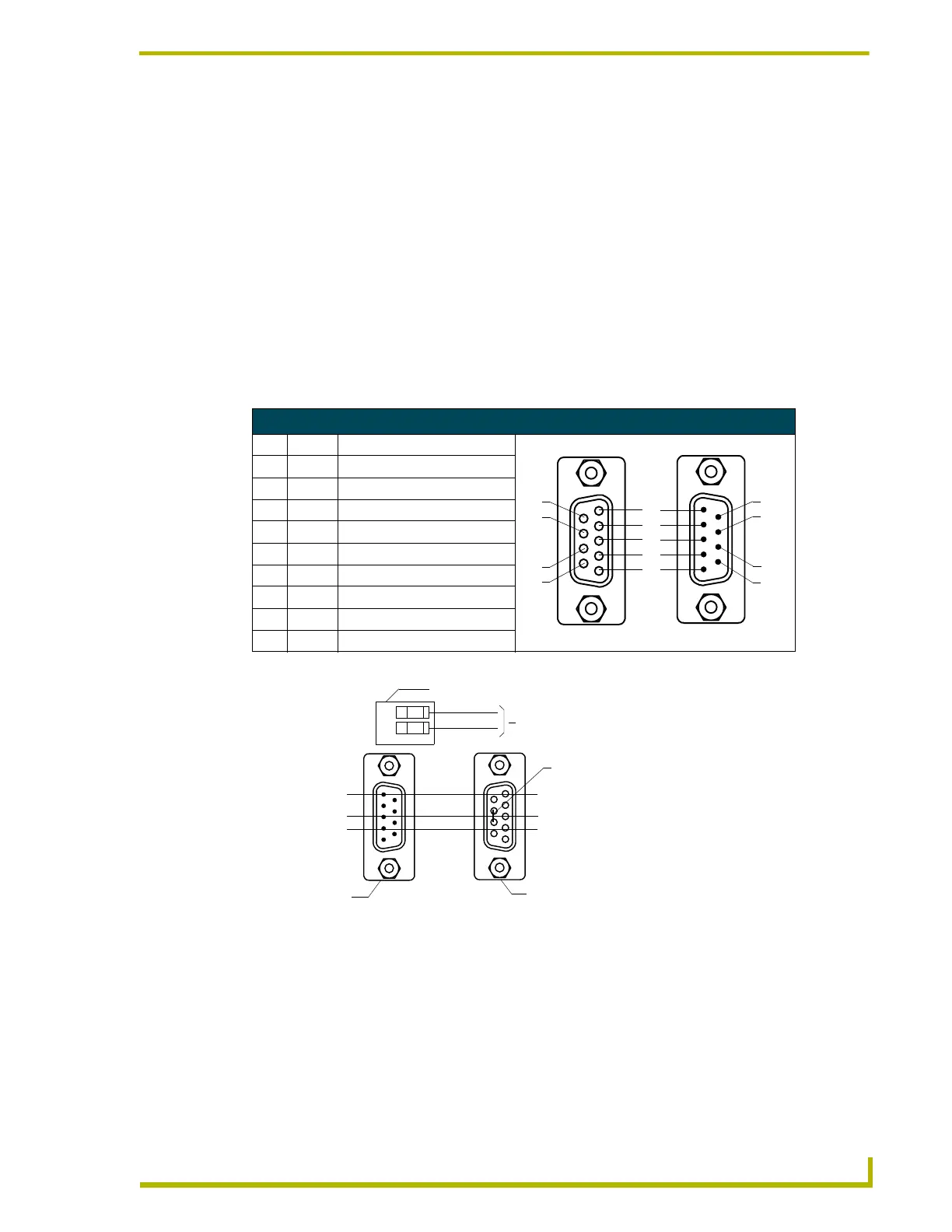
The following table lists the (DB-9) RS-232 connector pinouts; FIG. 6 shows the (DB-9)
RS-232 connector and power supply wiring diagram.
Using the VGA IN DB-15 (male) high-density connector
Connect the VGA source equipment’s DB-15 (female) connector to the VGA IN DB-15 (male)
high-density connector on the rear panel of the touch panel. The following table below lists the
VGA IN DB-15 connector pinouts.
(DB-9) RS-232 Connector Pinouts
Pin Signal Function
1 N/A Not used
2 RXD Receive data
3 TXD Transmit data
4 DTR Data terminal ready (not used)
5 GND Signal ground
6 DSR Data set ready (not used)
7 RTS Request to send (not used)
8 CTS Clear to send (not used)
9 N/A Not used
FIG. 6 DB-9 RS-232 connector and power supply wiring diagram
9
8
7
6
5
4
3
2
1
9
8
7
6
Female
Male
Power connector
Mouse or PC, DB-9 connector
Female
Male
TPI
DB-9 connector
Optional 7 to 8-pin
connector
2 (RXD)
3 (TXD)
5 (GND)
2 (RXD)
3 (TXD)
5 (GND)
+ (PWR)
- (GND)
+
12 VDC power supply
 Loading...