Configuring Communication
23
MVP-5100/5150 5.2" Modero Viewpoint Touch Panels
Configuring Communication
Overview
All control for a MVP-5150 touch panel is established through a NetLinx Master. Communication
between the MVP and the Master consists of using either Wireless Ethernet (DHCP, Static IP) or USB.
References to Ethernet in this manual focus on the use of Wireless Ethernet via the MVP-5150’s WiFi
Card. Configuration for a MVP-5100 touch panel is made through the mini-USB port, as it does not have
a WiFi Card.
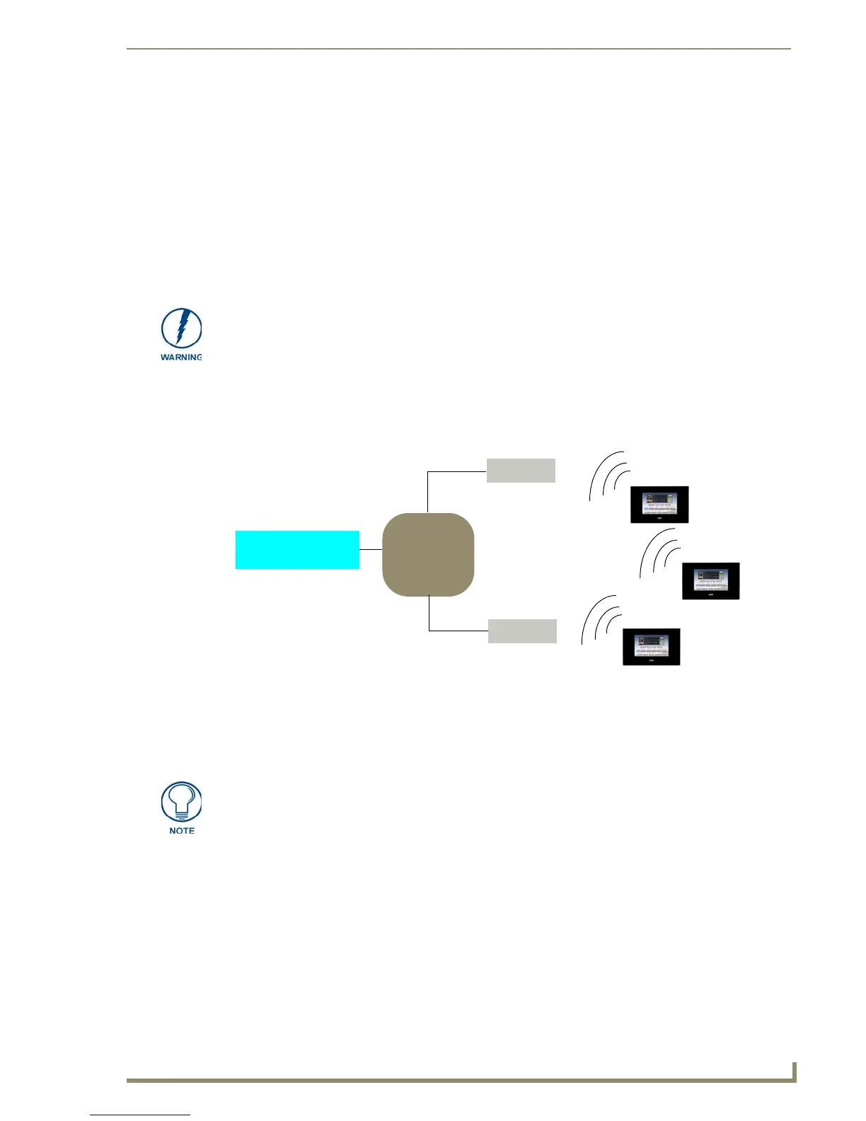
In the example below (FIG. 11), three MVP-5150 devices are shown at varying distances from the two
AP gateways. As with any other AP network, the gateways are spaced so as to allow a maximum
wireless coverage for the three devices.
When initially installing a MVP-5150, some basic configuration items, including network settings and
NetLinx settings, will need to be set. For more information, refer to the Protected Setup Pages section on
page 53.
IR Communication
Both the MVP-5100 and MVP-5150 may be used as infrared remote devices for other AMX controllers
or third-party devices. The devices can transmit IR over 20 feet (6.10 m) from the panel at frequencies of
38KHz and 455KHz, as well as up to eight user-programmed frequencies between 20KHz and 1.5MHz.
IR receivers and transmitters on G4 panels share the device address number of the panel.
Both devices include an IR transmitter for communication between devices. The transmitter is located
behind the IR Emitter Panel on the back of the device.
Before commencing, verify you are using the latest NetLinx Master and
Modero panel-specific firmware. Verify you are using the latest versions of AMX’s
NetLinx Studio and TPDesign4 programs. Attempting uploads of drivers and firmware
with older versions of NetLinx Studio and TPDesign4 will fail.
FIG. 11 System Deployment Diagram
Network Master
IP
Network
802.11g AP
802.11g AP
Panel 1
Panel 2
Panel 3
The MVP-5150 defaults to Auto mode for its Master connection.
 Loading...