Overview
19
Hardware Reference Guide - NX-Series NetLinx Integrated Controllers
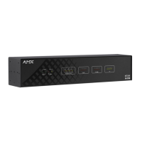
NX-4200 Specifications
NX-4200 Specifications
Dimensions (HWD): 1.766" x 17" x 9.18" (44.85mm x 431.8mm x 233.17mm)
RU: 1
Active Power
Requirements:
• DC input voltage (typical): 12 V
DC
• DC current draw: 200 mA @ 12 V
DC
• DC range, voltage: 9-18 V
DC
• AC voltage (typical): 100-240V
AC
50/60Hz
Active Power
Consumption:
8.4W
Memory: • 1 GB RAM
• 1 MB Non-volatile RAM (NVRAM)
• 8 GB Internal MicroSD memory card
Weight: 7.6 lbs (3.4473 kg)
Enclosure: Metal with black matte finish
Certifications: • FCC CFR Title 47 Part 15
• CE EN 55022
• CE EN 55024
• CE EN 60950-1
• IEC 60950-1
•UL 60950-1
•C-Tick CISPR 22
• IC CISPR 22
•VCCI CISPR 22
• RoHS / WEEE compliant
Front Panel Components:
Power: Press the Power button to power on or power off the controller. Hold for 2 seconds to power off. Momentary
press to power back on.
Program Port 1 Type-B USB port that can connect to a USB port on a PC and access the NetLinx Studio program for
controller configuration.
USB Port 1 Type-A USB port for connecting a mass storage device for loading .tkn files, reading or writing configuration
files and log files, or updating the firmware on the unit.
Display Control Button 1 rocker-style tactile button for stepping through the supported status parameters displayed on the front
panel LCD.
LCD Display A 2 line by 20 character alphanumeric display for viewing status parameters.
Front Panel Components: (Cont.)
Master LEDs: • LINK/ACT (green): Blinks when the Ethernet cables are connected and terminated correctly. Also blinks
when receiving Ethernet data packets.
• STATUS (green): Blinks to indicate that the system is programmed and communicating properly.
• OUTPUT (red): Blinks when the Controller transmits data, sets channels On and Off, sends data strings, etc.
• INPUT (yellow): Blinks when the Controller receives data from button pushes, strings, commands, channel
levels, etc.
ICSLAN LEDs 4 LEDs which blinks when the RJ-45 cables to ports 1-4 are connected and terminated correctly. The LEDs
also blink when receiving LAN data packets.
Serial LEDs (red): 2 sets of eight LEDs, each of which light to indicate that the corresponding RS-232 ports (2-4, 6-8) and
RS-232/422/485 ports (1, 5) are transmitting or receiving RS-232, 422, or 485 data.
Relay LEDs (red): 1 set of 8 LEDs, each of which light to indicate the corresponding relay channels (1-8) are active (closed).
These LEDs reflect the state of the relay on port 21.
IR/Serial LEDs (red): 1 set of 8 LEDs, each of which light to indicate the IR/Serial channels 1-8 are transmitting control data on the
corresponding IR/Serial ports (ports 11-18). The LED indicator for each IR port remains lit for the length of
time that IR/Serial data is being generated.
Digital I/O LEDs (yellow): 1 set of 8 LEDs, each of which light when the corresponding rear I/O channels (1-8) are active. The LED for
each I/O port reflects the state of that particular port.
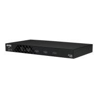
Rear Panel Components:
RS-232 (Ports 2-4, 6-8) 6 5-pin RS-232 control ports using 5-pin 3.5 mm mini-Phoenix (male) connectors with XON/XOFF (transmit
on/transmit off), CTS/RTS (clear to send/ready to send). Supports 150-115,200 baud.
RS-232/422/485
(Ports 1, 5):
2 10-pin RS-232/422/485 control ports using 10-pin 3.5 mm mini-Phoenix (male) connectors with XON/
XOFF (transmit on/transmit off), CTS/RTS (clear to send/ready to send). Supports 150-115,200 baud.
 Loading...