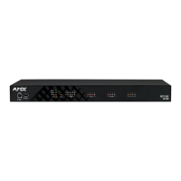
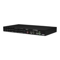
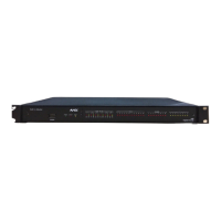
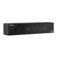
Overview
21
Hardware Reference Guide - NX-Series NetLinx Integrated Controllers
Serial, IR, AxLink, and PoE Port Diagnostics
When a string is sent to a serial port or an IR pulse to an IR port, the X-Series controllers can detect and report if the port being
used is in a fault condition. The controllers can also detect certain fault conditions on the AxLink bus or Power-over-Ethernet (PoE)
subsystem. The following fault conditions are recognized:
The serial cable is not connected
The Serial pin is connected to another pin
The IR emitter is not connected
The IR emitter is wired backwards
One or both AxLink bus data pins are shorted to power or ground
The maximum power for all PoE ports (72W) has been exceeded or the power supply voltage is outside of the
recommended limits
The maximum current for a single PoE port has been exceeded or the load has disconnected from an individual port
On the first attempt to use a port that is in a fault condition, the controller will do the following:
Quickly flash the front panel LED of the port being used 10 times
Generate an ONERROR data event in NetLinx
Report the error to any Duet Module that has claimed the port
Report the error to RMS if the controller is connected to an RMS server
Set an error flag for that port
The status of the error flag can be queried using the GET FAULT NetLinx command, which will result in a DATA EVENT where the
return status can be parsed.
NOTE: If the fault condition persists, subsequent attempts to use the same port will only result in the quick flashing of the front panel
LED. The ONERROR event and Duet Module or RMS reports only occur on the first attempt after booting the device or after the fault
status is cleared. This prevents a flood of redundant error messages when a faulted port is used continuously.
The fault status is cleared on a successful transmission over the port, and also can be cleared manually using the CLEAR FAULT
NetLinx command.
For serial and IR ports, an error condition is only checked at the time the port is used, so unused serial and IR ports will not
generate errors. AxLink bus errors are checked at boot time.
Mounting the Controller
Use the rack-mounting brackets (supplied with the NX-2200/3200/4200) for equipment rack installations. Remove the mounting
brackets and apply the rubber feet to the bottom of the controller for flat surface installations.
Installing the Controller into an Equipment Rack
The NX-2200/3200/4200 each ship with removable rack ears for installation into an equipment rack. The following instructions
apply to the NX-2200/3200/4200.
Rack Mount Safety Instructions
Be sure to follow these important safety instructions when installing your central controller:
If installed in a closed or multi-unit rack assembly, the operating ambient temperature of the rack environment may be
greater than room ambient. Therefore, consideration should be given to installing the equipment in an environment
compatible with the maximum ambient temperature 60°C (140°F).
Installing the equipment in a rack should be such that the amount of air flow required for safe operation of the equipment
is not compromised.
Mounting the equipment in the rack should be such that a hazardous condition is not achieved due to uneven mechanical
loading.
Consideration should be given to the connection of the equipment to the supply circuit and the effect that overloading of
the circuits might have on over current protection and supply wiring. Appropriate consideration of equipment nameplate
ratings should be used when addressing this concern.
Reliable earthing of rack-mounted equipment should be maintained. Particular attention should be given to supply
connections other than direct connections to the branch circuit (e.g. use of power strips).
NOTE: To avoid repeating the installation, test the incoming wiring by connecting the Controller’s connectors to their terminal
locations and applying power. Verify that the unit is receiving power and functioning properly. Disconnect the terminal end of the
power cable from the connected 12 VDC-compliant power supply.
 Loading...

