11
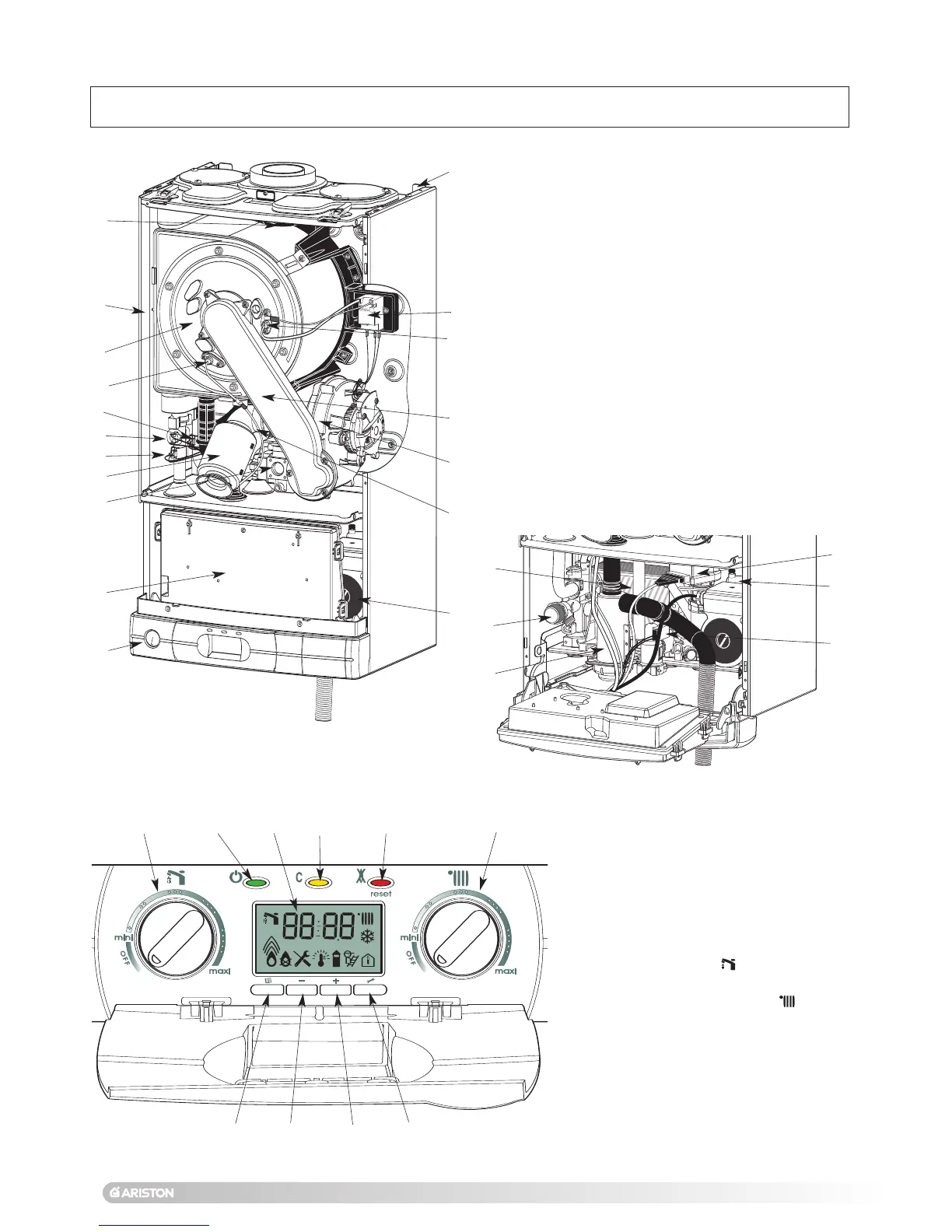
1.
- Steel chassis complete with expansion vessel
2.- Sealed chamber
3.- Burner and heat exchanger assembly
4.- Air / gas connection
5.
- 24 V modulating fan
6.- Gas valve
7.
- Ignition electrode
8.- Ionisation probe
9.
- Ignitor
10.- Combustion products manifold
11.- Condense trap
12.- Silencer
1
3
.
- Electrical box
14.- Pump
15.- Secondary heat exchanger
16.- Pressure gauge
17.- Three way valve
18.- Automatic air vent
19 - Domestic hot water flow switch
20.- Primary flow thermistor
21.- Primary return thermistor
22.- Overheat sensor
23.- Central heating pressure relief valve
1
2
3
4
5
6
8
12
13
14
30
26
27
25
34
28
INSTALLER INSTRUCTIONS
7
Fig. 5
Fig. 7
15
20
21
10
17
9
Fig. 6
33
31
32
19
18
22
16
29
25.- Display
26.-
On/off push button and power on
indicator light
27.- Yellow indicator - Comfort button
28.- Reset push button and red indicator
lock-out light
29.- DHW control knob and temperature
setting
30.- Central Heating control knob
and
temperature setting
31.- Menu button
32.- Reducing button
33.- Increasing button
34.- Setting button
42
7. Description
11
23
 Loading...