45
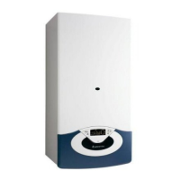
18.2.2 Removing the burner
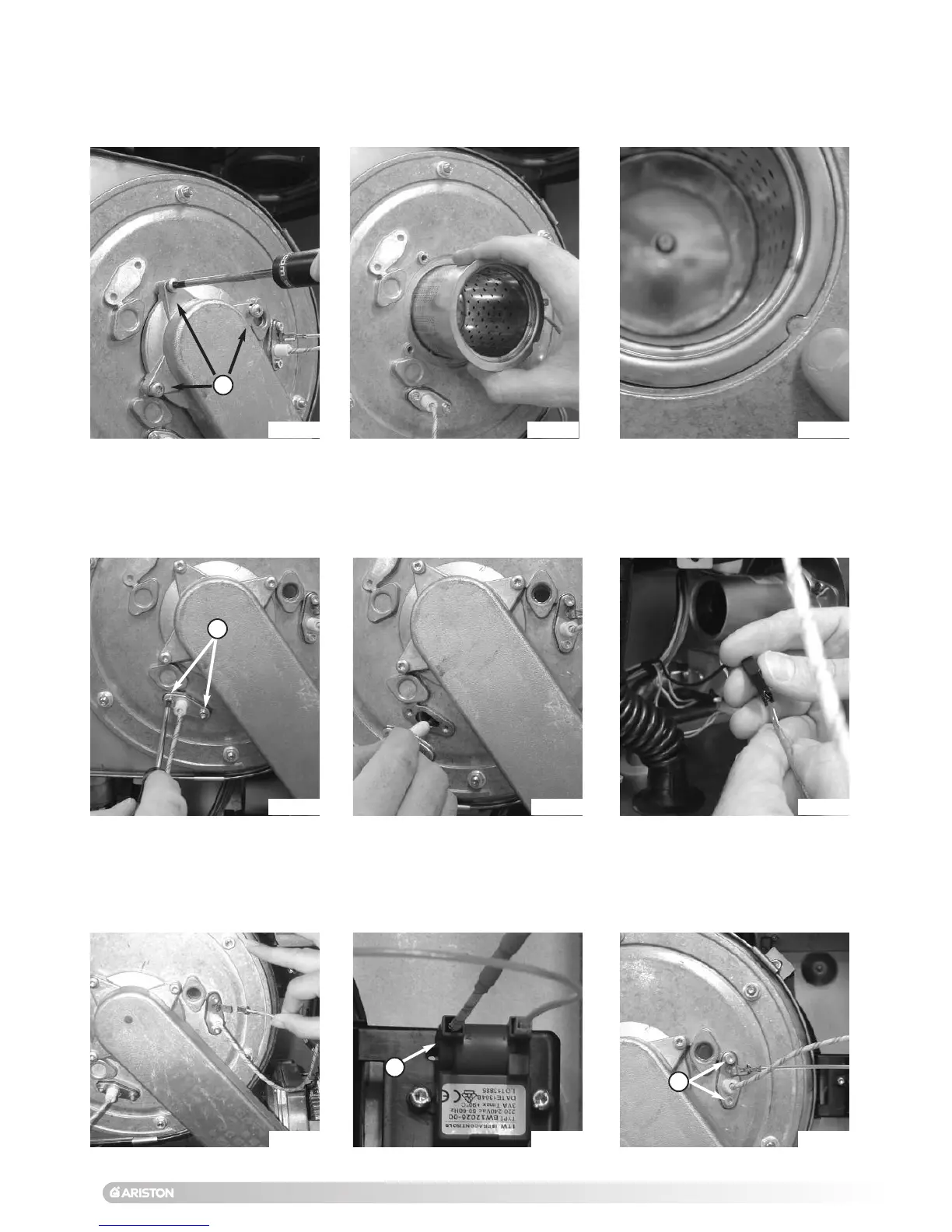
18.2.3 Removing the detection electrode
F
1. Carry out step 18.1.1 and 18.2.1;
2
.
R
emove the 3 screws
F f
rom the
air/gas manifold (Fig. 57)
;
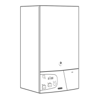
3. Slide the burner out from the
f
ront, taking care not to damage the
insulation (Fig. 58);
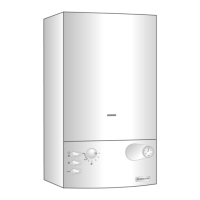
4. Reassemble in reverse order and
c
hecking all seals are undamaged
and the burner is positioned
c
orrectly (Fig. 59).
1. Carry out step 18.1.1;
2. Remove the 2 screws G from the
electrode manifold (Fig. 60);
3. Pull the electrode from the
combustion chamber (Fig. 61);
4. Disconnect the detection electrode
cable (Fig. 62).
5. Reassemble in reverse order.
18.2.4 Removing the ignition electrode
1. Carry out step 18.1.1;
2. Remove the earth cable from the
electrode (Fig. 63);
3. Remove the electrode cable H from
the ignitor (Fig. 64);
4. Unscrew the 2 screws I on the
electrode (Fig. 65);
Fig. 57
Fig. 58
Fig. 59
Fig. 60
Fig. 61 Fig. 62
Fig. 63 Fig. 64 Fig. 65
G
H
I
 Loading...