51
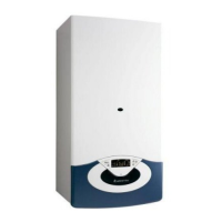
18.3.11 Removing the pressure switch
1. Remove the casing as in step 18.1.1 and drain down as
in step 18.3.1;
2. Pull off the connections. Then remove the pressure
switch by releasing it’s securing clip (see Fig. 98).
Fig. 98
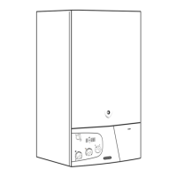
18.3.10 Removing the pressure gauge
1. Carry out steps 18.1.1 and 18.3.1;
2
.
R
emove the pressure gauge by releasing the two clips
V
and pulling the pressure gauge out. (see Fig. 97)
Fig. 97
V
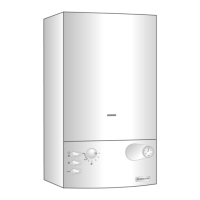
18.4 Access to the Control System
18.4.1 Removing the P.C.B.s
Fig. 99
Fig. 100
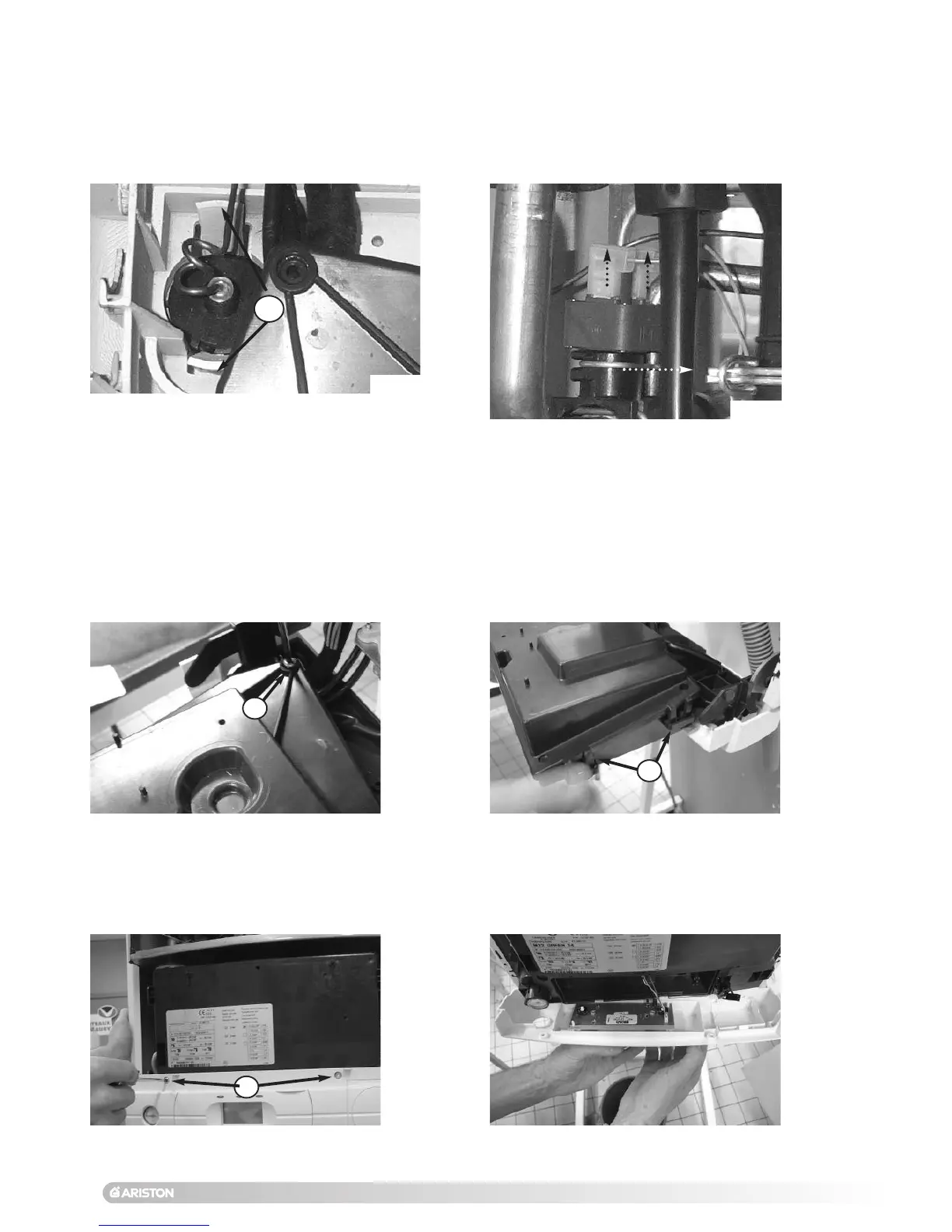
Fig. 101
Fig. 102
W2
W1
W3
3. Release the three clips W2 and remove the electrical box
cover (see Fig. 100);
1. Carry out steps 18.1.1 and 18.1.2;
2. Remove the screw W1 from the electrical box (see Fig.
99
);
5. Remove all electrical connections from the display PCB
(see Fig. 102);
4. Remove the two screws W3 from the front control panel
and lower the front control panel (see
Fig. 101);
 Loading...