49
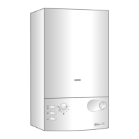
18.3.5 Removing the pump
1. Carry out step 18.1.1;
2. Lower the electrical box cover as in step 18.1.2;
3.
Remove the PCB cover;
4. Remove the pump plug from the control board and earth
plug from earth socket (see Fig. 91)
Fig. 91
Fig. 92
Fig. 93
Fig. 94
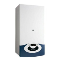
18.3.4 Removing the secondary heat exchanger
1. Carry out step 18.1.1 and 18.1.2;
2. Remove the 3 way valve motor as in step 18.3.2;
3
.
D
isconnect the expansion vessel pipe.
S2
S3
Fig. 89
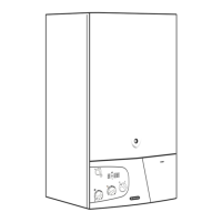
R
Fig. 90
4. Unscrew the two fixing screws R and pull the heat
e
xchanger toward you
(
see Figs. 89 & 90)
;
5. Reassemble in reverse order;
T
he heat exchanger is so designed that it cannot be
remounted incorrectly;
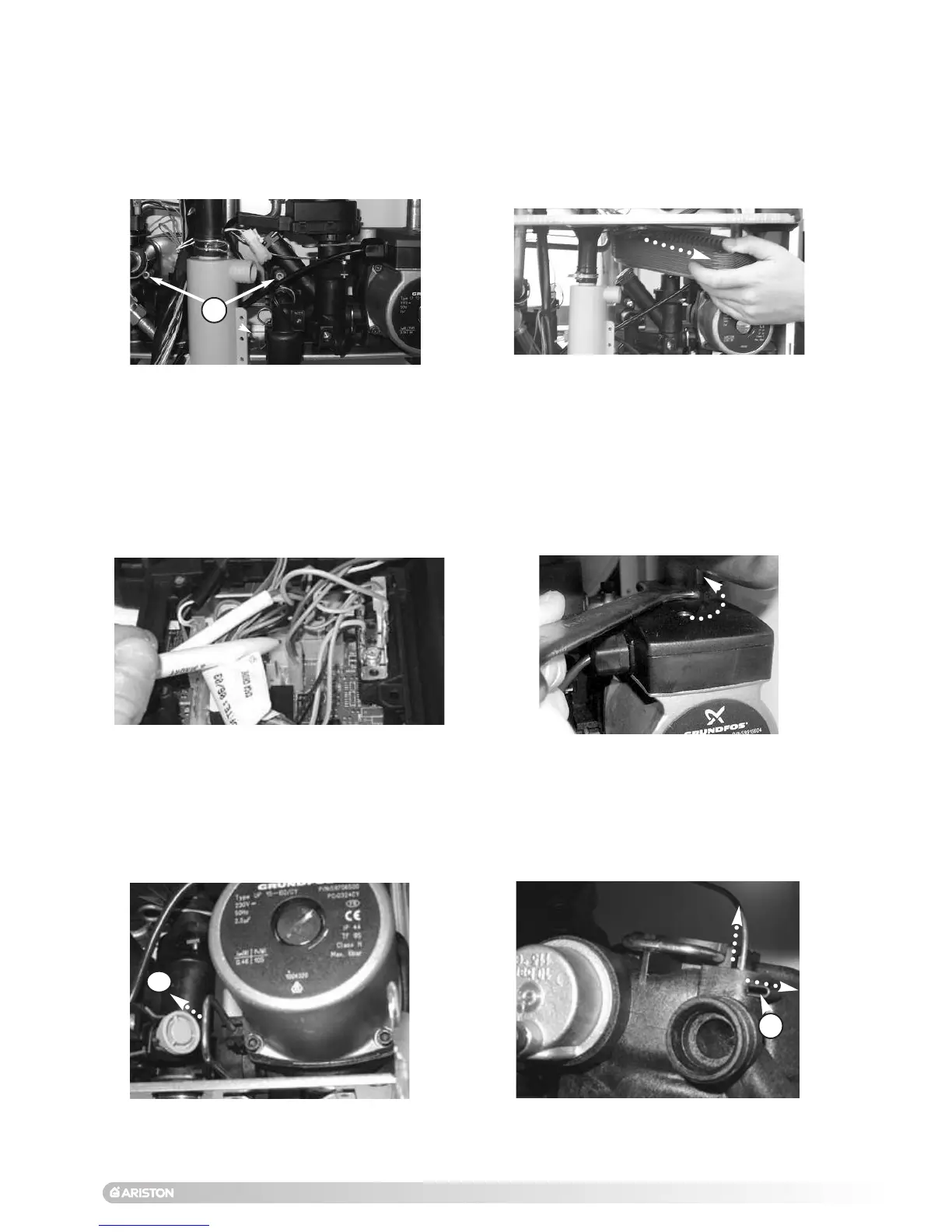
5. Unscrew the pump nut (see Fig. 92);
6. Remove the clip S2 on the pump volute (see Fig. 93);
7. Pull the pump toward you and remove the clip S3 securing
the pressure gauge
(see Fig. 94);
8. Reassemble in reverse order.
 Loading...