48
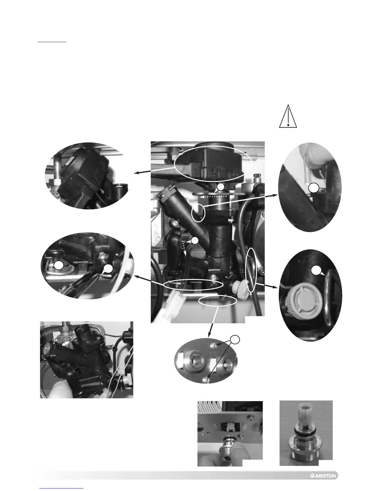
18.3 Access to the Water Circuit
Important! Before any component is removed, the boiler must be drained of all water.
18.3.3 Removing the float of the flow switch
1. Carry out step 18.1.1 and 18.1.2;
2. Disconnect the wire from the 3 way valve;
3
.
R
emove the clip “
P
2
”
and the 3 way valve motor
(
see Figs. 80 and 81)
;
4. Unscrew the two screws “P3” (Fig. 85) and remove the 4 clips “Q1* - Q4”
(see Figs. 82 to 84);
5. Remove the 3 way valve body by pulling it toward you (see Fig. 86);
6
.
R
eassemble in reverse order;
18.3.1 Drain down
DHW : close the DHW inlet tap and open a tap on the installation / CH : Close the flow and return isolating valve and
open the pressure relief valve.
P1
P3
P2
Q1
Q2
Q3
Q4
Fig. 85
Fig. 80
Fig. 82
Fig. 83
Fig. 84
Fig. 81
Fig. 86
*
See the
paragraph
18.3.1 before
removing the
clips.
1
8.3.2 Removing the 3 way valve
1. Remove the clip “Q1” fixing the brass connector (see Fig. 82);
2. Disconnect the connecting pipe;
3. Pull down the brass connector and catch simultaneously the
float (see Figs. 87 &
88);
4. Reassemble in reverse order;
Fig. 87
Fig. 88
 Loading...