30
14. Commissioning and testing (continued)
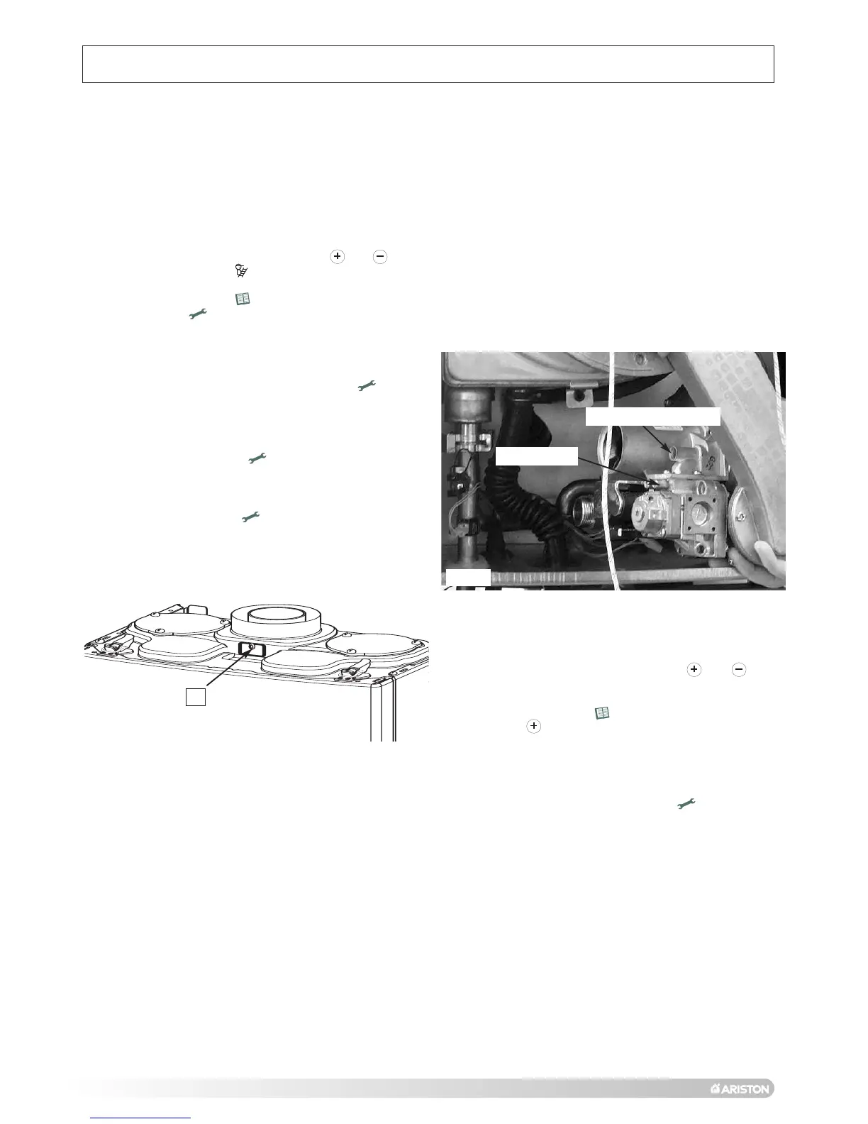
14.3 Adjusting the CO2
Adjustment screw
Fig. 37
Q
Fig. 36
1
. Remove the casing panel as described in Section 18.1
(page 43);
2. Connect a manometer to the inlet test nipple on the gas
valve, turn on a hot tap and ensure the inlet working
p
ressure is 20mbar. If correct proceed as follows;
3. Turn on the combustion analyser, remove the combustion
t
est point plug
Q (
Fig. 36) and insert the analyser probe
into the test point;
4
. Turn on a hot tap and ensure that the boiler is firing.
5. Access the setting menu by pressing the and
keys for 5 seconds the icon will be shown in the
display;
6. Press the menu button four times to access Menu 5
and press the setting button once to switch the output
of the boiler to maximum (two digits will be flashing
indicating the temperature of the boiler). There will be a
cursor at the top of the display indicating the boiler is at
maximum output. If the cursor is at the bottom of the
display (indicating minimum output) press the button
the change to maximum output;
7. If necessary adjust the screw on the gas valve (Fig. 37) to
set the CO
2 to 8.9% +/- 0.2% (NG) or 9.7% +/- 0.2%
(LPG);
8. Press the setting button once to set the combustion
control rate mode to minimum, and, if necessary, adjust
the screw on the gas valve to set the CO2 to 8.9% +/-
0.2% (NG) or 9.7% +/- 0.2% (LPG);
9. Press the setting button again to set the combustion
rate control mode to maximum and if necessary adjust
the screw on the gas valve to set the CO
2 to 8.9% +/-
0.2% (NG) or 9.2% +/- 0.2% (LPG);
10. Reassemble in reverse order.
14.4 Gas Conversion
To convert from Natural Gas (G20) to LPG (G31), it is
n
ecessary to insert a diaphragm and restrictor between the
gas valve and air/gas arm.
Once the conversion has been made, the CO
2 setting will
need to be checked as described in Section 14.3, for LPG
the CO2 reading should be 10% +/- 0.2% with the front case
f
itted).
To convert from LPG (G31) to Natural Gas (G20), it is
necessary to remove the diaphragm and restrictor from
between the gas valve and air/gas arm.
Once the conversion has been made, the CO
2 setting will
need to be checked as described in Section 14.3, for NG the
CO
2 reading should be 9.2% +/- 0.2% (with the front case
fitted).
14.6 Fitting the external sensor
14.5 Range rating the maximum heating
power
To adjust the maximum heating power it is necessary to
access the settings menu by pressing the and
buttons together for five seconds, and proceed as follows;
1. Press the menu button 3 times to access Menu 4;
2. Press the button to access Menu 4.9;
3. The value is adjustable between 0 and 10, 0 being the
minimum output and 10 being the maximum, please refer
to the chart on page 33 (Fig. 40) for the required setting;
4. The maximum central heating output can now be
adjusted by pressing the setting button ;
5. To exit the setting mode, do not press any buttons for 1
minute, the boiler will automatically exit the Setting Menu.
The external sensor should be fitted 1.5 meters above the
floor on a North to North West facing wall, out of direct
sunlight.
To connect the external sensor, it is first necessary to
remove the casing panel as described in Section 18 (page
42);
Remove the PCB cover as described in Section 18.4 and
connect the external sensor as described in Section 18.5
(page 50).
Test nipple
 Loading...