27
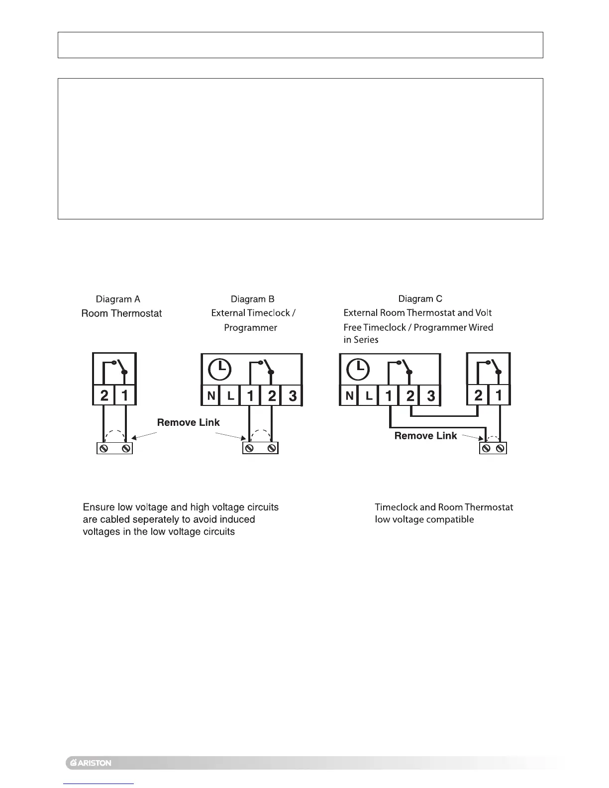
- If a remote time clock is to be fitted, using a volt-free switching time clock, remove the link wire and connect the
switching wires from the time clock following points above (see also
Diagram B Fig. 30).
-
If using an external time clock and room thermostat, remove the link wire and connect in series as above (see also
D
iagram C Fig. 30
)
.
Live and Neutral connections to operate the clock motor must be taken from a suitable source.
Connector
11 (Fig. 30), is used by the mechanical time clock supplied with the boiler or for the optional digital programmer, for
fitting instructions, please refer to those provided with the clock or page 28 of this manual.
Fig. 30
CONNECTOR 12 ON
PCB, SEE FIG. 31
13. Electrical connections (continued)
CONNECTOR 12 ON
PCB, SEE FIG. 31
CONNECTOR 12 ON
PCB, SEE FIG. 31
 Loading...