Description
Air drawn through filter (AF) and open inlet valve (IV) into compressor element (E) is compressed. A mix
of compressed air and oil flows into the air receiver/oil separator (AR) via check valve (CV). The air is
discharged through outlet valve (AV) via minimum pressure valve (Vp) and air cooler (Ca).
The air cooler is provided with a moisture trap (MT).
On Full-Feature compressors, the air flows through air dryer (DR) before it is discharged through outlet
valve (AV). Also see section Air dryer.
During loaded operation, minimum pressure valve (Vp) keeps the pressure in the separator tank (AR)
above a minimum value, required for lubrication. An integrated check valve prevents the compressed air
downstream the valve from being vented to atmosphere during unloaded operation. When the compressor
is stopped, check valve (CV) and inlet valve (IV) close, preventing compressed air (and oil) to be vented
into the air filter.
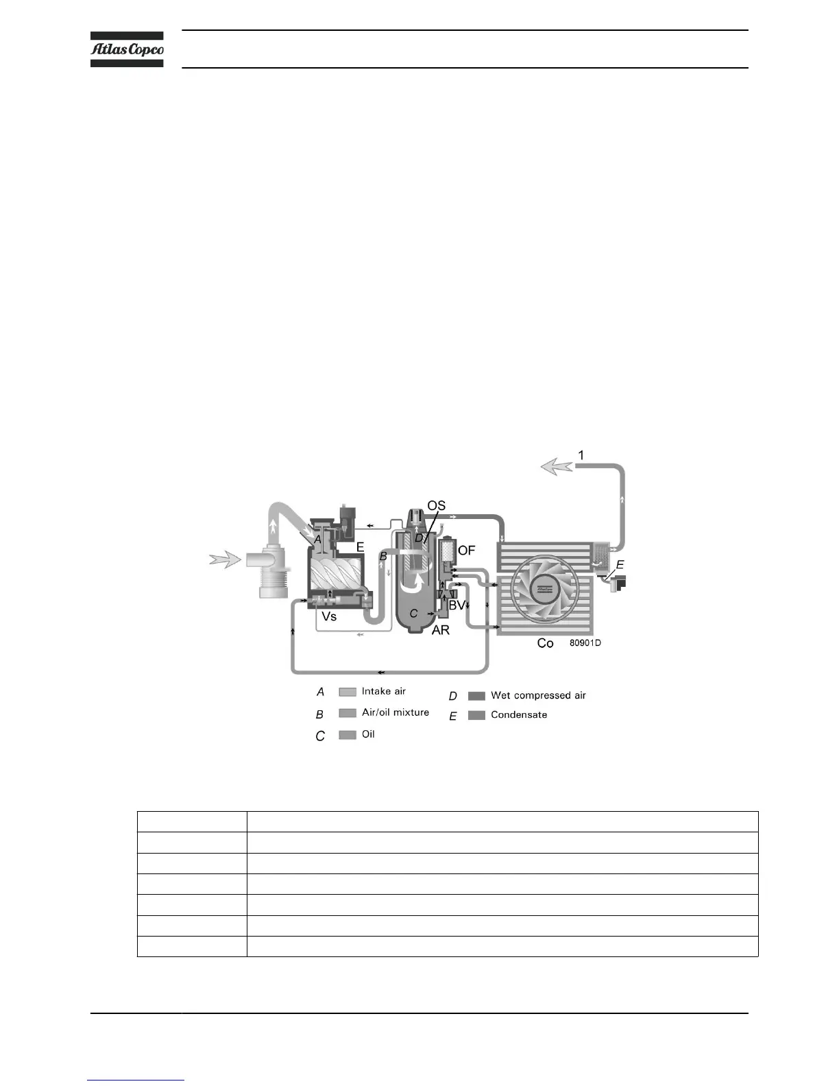
2.3 Oil system
Flow diagram
Oil system
References Description
1 Compressed air flow to the air dryer (compressors with integrated dryer)
A Intake air
B Air/oil mixture
C Oil
D Wet compressed air
E Condensate
Instruction book
14 API603130