2.9 Air dryer
Flow diagram
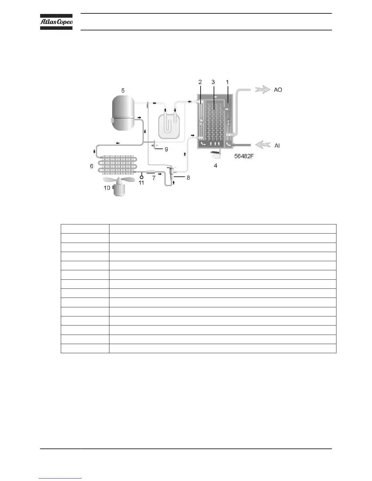
Air dryer
Reference Name
AI Air inlet
AO Air outlet
1 Air/air heat exchanger
2 Air/refrigerant heat exchanger/evaporator
3 Condensate separator
4 Automatic drain / condensate outlet
5 Refrigerant compressor
6 Refrigerant condenser
7 Liquid refrigerant dryer/filter
8 Thermostatic expansion valve
9 Bypass valve
10 Condenser cooling fan
11 Pressure switch, fan control
Compressed air circuit
Compressed air enters heat exchanger (1) and is cooled by the outgoing, cold, dried air. Water in the
incoming air starts to condense. The air then flows through heat exchanger/evaporator (2), where the
refrigerant evaporates, causing the air to be cooled further to close to the evaporating temperature of the
refrigerant. More water in the air condenses. The cold air then flows through separator (3) where all the
condensate is separated from the air. The condensate is automatically drained through outlet (4).
The cold, dried air flows through heat exchanger (1) where it is warmed up by the incoming air.
Instruction book
22 API603130

 Loading...