- 62 -
9 Options available
9.1 Circuit diagrams
The engine control circuit diagrams and the power
circuit diagrams for the standard QES 9-14-20-30-40
and QES 11-16-25-35-50 units, for the units with
options and for the units with combined options are:
Circuit 1ph
Unit Circuit
QES 9-11 Kd 1636 0050 77
QES 14-20-30-40/16-25-30-50 Kd 1636 0050 25
Circuit 2ph
Unit Circuit
QES 9-11 Kd 1636 0053 37
QES 14-20-30-40/16-25-30-50 Kd 1636 0049 62
Circuit 3ph
Unit Circuit
QES 9-11 Kd 1636 0051 72
QES 14-20-30-40/16-25-30-50 Kd 1636 0048 31
9.2 Overview of the electrical
options
The following electrical options are available:
– Automatic battery charger
– Battery switch
– Engine coolant heater
– Single phase
–Dual phase
– Outlet sockets (S) - 3-phase
–IT-relay
9.3 Description of the electrical
options
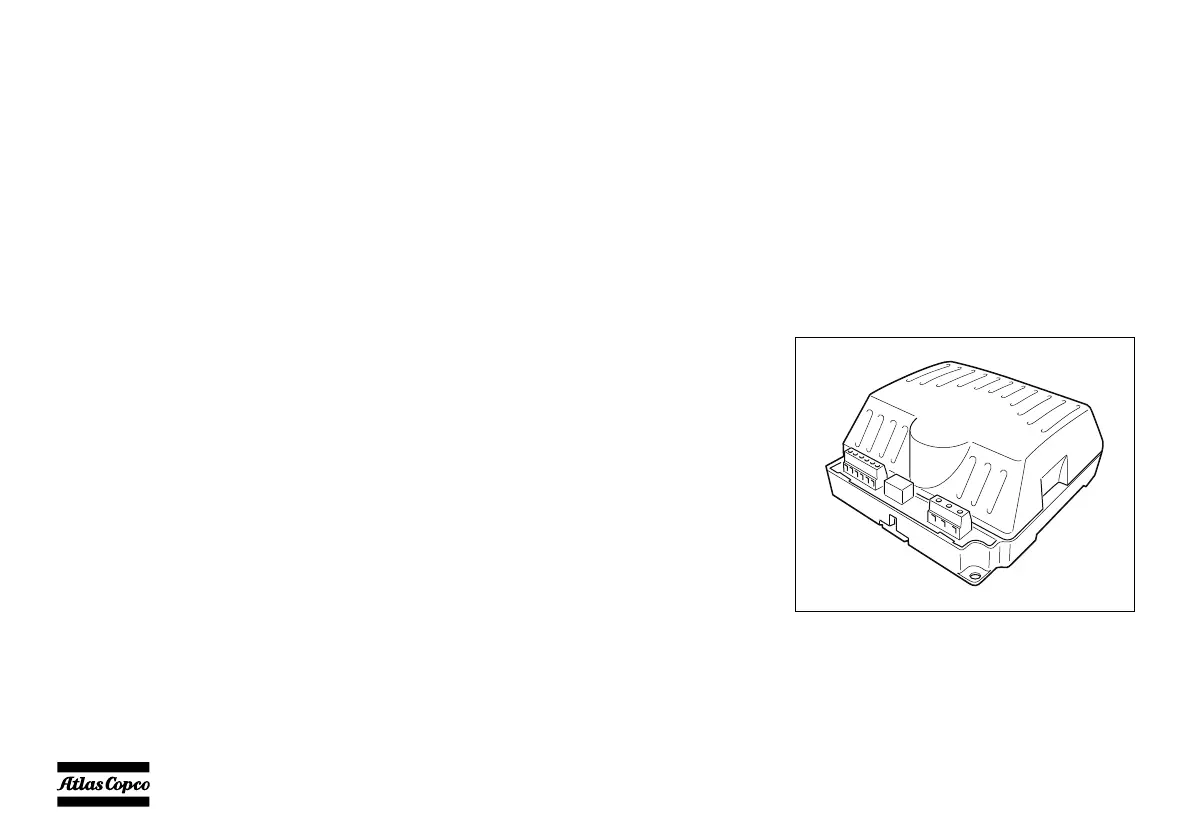
9.3.1 Automatic battery charger
The 2 Amp battery chargers have been designed to be
permanently connected to a battery, keeping it
charged to maximum capacity. The charger will
continue to operate during cranking and running. It
can accept multiple AC voltage connections.
The LED on the bottom indicates that the unit is
operational.

 Loading...


