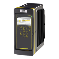
User guide EN TPS Control
44
© Atlas Copco Industrial Technique AB - 9836 5819 01
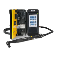
Pneumatic monitoring and controlling
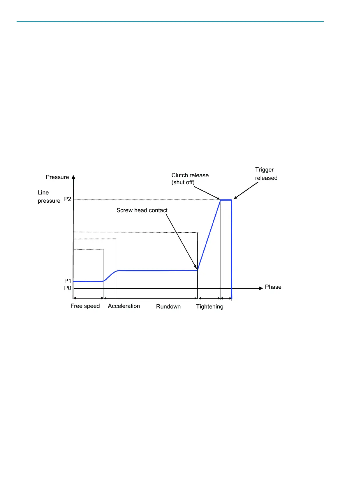
Air tools with reporting functionality are equipped with a pneumatic signal output that indicates which
phase of the tightening cycle the tool has reached, by means of variations in air pressure (see figure be-
low). The pneumatic signal is located between the start valve and the shutoff valve of the driver and is car-
ried through a small signal tube to two external pressure sensors. The pressure sensors produce digital
signals used for controlling the air supply to the tool using a magnetic valve.
For TPS Control to function properly with air tools, it requires a stable air-line system without too much
pressure fluctuations. You must therefore install a pressure gauge as close as possible to the TPS pneu-
matic system and for an optimal air signal, make sure the air cable length is no more than two meters.
To get significant pressure value difference between different tightening sequences, make sure that there
are no leakages in the couplings and tubes.
The pneumatic signal is monitored during a programmable time window, defined by the air option parame-
ters as descibed in Parameters>Air option parameters [Page000].
The phase Free speed mentioned in the figure above is not relevant for normal tightening operations, it is
only used when programming pressure sensor B1 (see Programming pressure sensors [Page000]).
In the TPS Control timers are triggered when certain pressure levels are reached:
■
Pressure level 1 (P1) = Trigger pressed in by operator
■
Pressure level 2 (P2) = Clutch release at the correct tightening torque
If the tightening operation cannot be completed within the programmed time window, an error signal is trig-
gered. Error handling is described further in section Troubleshooting [Page000].

 Loading...