Installation Manual 12 Document #: LTRT-83506
Mediant 1000
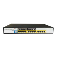
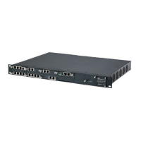
Table 2-1: Front Panel Component Descriptions
Item #
Label/
Module
Component Description
1
FXO
(Optional) FXO and FXO G module: The device can house up to six FXO
modules. Each module provides four RJ-11 ports. Therefore, up to 24 FXO
ports (i.e., 6 modules x 4 ports) are supported.
Note: The standard FXO module supports outdoor and indoor (lightning
protection) loop-start signaling. The FXO G module supports both loop- and
ground-start signaling (but only supports indoor protection). To enable
ground-start signaling, use the ini file parameter GroundKeyDetection (refer to
the device's User's Manual).
FXS
(Optional) FXS module: The device can house up to six FXS modules. Each
module provides four RJ-11 ports. Therefore, up to 24 FXS ports (i.e., 6
modules x 4 ports) are supported.
Note: The FXS modules support both loop- and ground-start signaling.
TRUNKS
(Optional) TRUNKS module: The device supports up to four digital E1/T1/J1
trunks. The modules are available in 1- or 2- or 4-span configurations (RJ-48c
ports). If the power fails, a relay connects trunks 1 to 2, and 3 to 4 (in the
same module) acting as a fallback for PSTN trunk.
BRI
(Optional) BRI module: The device supports up to five BRI modules. Each
module provides up to four BRI line (RJ-45) ports, therefore, up to 20 BRI
ports are supported.
2
MPM
(Optional) Media Processing Module (MPM): The device supports up to three
MPM modules for IP media server capabilities (i.e., conferencing, and IP-to-IP
routing applications). These modules can be housed in slots 3, 4, 5, or 6,
depending on required configuration (for a detailed description of channel
resources using MPM modules, refer to the device's User's Manual).
3
CPU
Main CPU module.
4
CPU
This slot can either house a spare Central Processing Unit (CPU) module or
the Connection module (OSN server). For OSN Server installation, refer to
the device's User's Manual.
5
Power 1
(Optional) Spare Power Supply module slot. The device can provide two
extractable power supply units (Power 1 and Power 2). Each power supply
unit provides an AC power connector on its rear panel. If both Power 1 and
Power 2 units are used, the load is shared between them. This (optional)
load-sharing feature enables power failure protection (redundancy). When
using this feature, you are advised to connect each power supply unit to a
different AC supply circuit.
6
Power 2
Main Power Supply module (refer to the above description).
7
Schematic
Extractable Fan Tray module with a schematic displayed on its front panel
showing the chassis' slot numbers. The Fan Tray module cools the device's
components. For additional information, refer to 'Replacing the Air Filter' on
page 32.

 Loading...


