Home
AudioCodes
Gateway
MSBG Series
AudioCodes MSBG Series Installation Manual
4
of 1
of 1 rating
76 pages
Give review
Manual
Specs
To Next Page
To Next Page
To Previous Page
To Previous Page
Loading...
Installation Manual
62
Document #: LTRT-83506
Mediant
1000
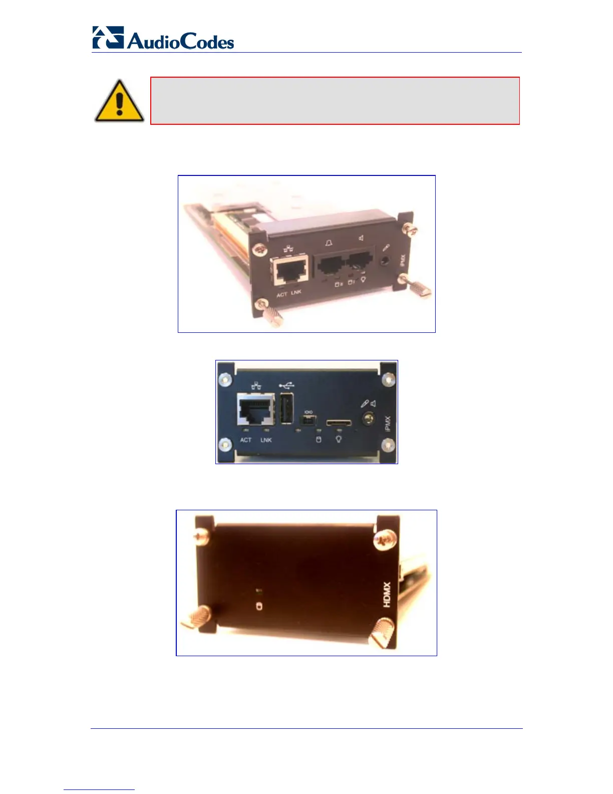
Note:
The CM module is applicable only to OSN1.
iPMX module (housed in the rear panel):
Figure
5-2: iPMX Module (Only for OSN1)
Figure
5-3: iPMX Module (For OSN2)
Hard Drive module (HDMX) (housed in the rear p
anel)
:
Figure
5-4: Hard Drive Module (HDMX)
61
63
Table of Contents
Default Chapter
3
Table of Contents
3
List of Figures
5
Abbreviations and Terminology
7
Customer Support
7
Weee Eu Directive
7
Related Documentation
8
1 Introduction
9
Figure 1-1: Summary of Steps for Installing the Device
9
2 Installing the Device
11
Physical Description
11
Front Panel
11
Figure 2-1: Front-Panel View and CPU Enlargement
11
Table 2-1: Front Panel Component Descriptions
12
Rear Panel
14
Unpacking Package Contents
14
Figure 2-2: Rear Panel
14
Table 2-2: Rear Panel Component Descriptions
14
Mounting the Device
15
Desktop Mounting
15
Figure 2-3: Attached Rubber Foot on Underside of Chassis
15
Figure 2-4: Location of Grooves for Rubber Feet
15
Installing the Device in a 19-Inch Rack
16
Figure 2-5: Peeled-Off Rubber Foot
16
Cabling the Device
18
Connecting to Earth (Ground)
19
Figure 2-6: Earthing the Device
19
Connecting to the IP Network
20
Figure 2-7: RJ-45 Connector Pinouts
20
Connecting to FXS/FXO Interfaces
21
Connecting the Analog Lifeline Phone
21
Figure 2-8: RJ-11 Connector Pinouts
21
Figure 2-9: RJ-11 Connector Pinouts for FXS Lifeline
22
Figure 2-10: Mediant 1000 Analog Lifeline Cable Setup
22
Table 2-3: FXS Lifeline Setup Component Descriptions
22
Connecting to ISDN BRI Lines
23
Figure 2-11: RJ-45 Connector Pinouts for BRI Ports
23
Connecting to E1/T1 Trunks
24
Figure 2-12: RJ-48C Connector Pinouts for E1/T1
24
Connecting to E1/T1 Trunks for PSTN Fallback
25
Figure 2-13: Mediant 1000 Digital Lifeline Cabling (E.g., Trunks 1 and 2)
25
Connecting to Dry Contact Relay Alarm System
26
Figure 2-14: Dry Contact Wires' Mate
26
Table 2-4: Dry Contact Operational Description
26
Connecting RS-232 Serial Interface to PC
27
Figure 2-15: RS-232 Cable Adaptor
27
2.4.10 Connecting to Power
28
Figure 2-16: Power Supply Module
28
Maintenance
29
I/O Module Slot Assignment
29
Figure 2-17: Mediant 1000 Front Layout
29
Replacing Modules
30
Figure 2-18: Recommended Priority Module Slot Assignment
30
Figure 2-19: Module Orientation in Chassis Top- and Bottom-Row Slots
31
Inserting Modules into Previously Empty Slots
32
Replacing the Air Filter
33
Figure 2-20: Slightly Extracted Fan Try Unit
33
Figure 2-21: Fan Tray with Filter Removed
34
3 Configuring the Device
35
Assigning an IP Address
35
Table 3-1: Default IP Addresses
35
Assigning an IP Address Using HTTP
36
Figure 3-1: Enter Network Password Screen
36
Assigning an IP Address Using Bootp
37
Assigning an IP Address Using the Voice Menu Guidance
38
Figure 3-2: Bootp Client Configuration Screen
38
Table 3-2: Configuration Parameters Available Via the Voice Menu
40
Assigning an IP Address Using the CLI
41
Configuring Basic SIP Parameters
42
Enabling Channels and Configuring Call Routing (Example)
43
Figure 3-3: Enabling Channels in Trunk Group Table Page
43
Figure 3-4: Routing Tel Calls to an IP Address
44
Configuring PSTN Trunks
45
Figure 3-5: Trunk Settings Page
45
Saving and Resetting the Device
47
Figure 3-6: Maintenance Actions Page
47
Changing Login User Name and Password
48
Figure 3-7: WEB User Accounts Page (for Users with 'Security Administrator' Privileges)
48
Backing up and Restoring Configuration
49
Figure 3-8: Configuration File Page
49
Restoring Factory Default Settings
50
Upgrading the Device
51
Software Upgrade Wizard
51
Figure 3-9: Start Software Upgrade Wizard Screen
52
Figure 3-10: Load CMP File Wizard Page
53
Figure 3-11: End Process Wizard Page
54
Loading Ini and Auxiliary Files
55
Table 3-3: Auxiliary Files Descriptions
55
Figure 3-12: Load Auxiliary Files Page
56
4 Monitoring the Device
57
Front-Panel Leds
57
Figure 4-1: Location of Front-Panel Leds
57
Table 4-1: Analog I/O (FXS / FXO) Modules Leds Description
57
Table 4-2: E1/T1 PRI I/O TRUNKS Modules LED Description
57
Table 4-3: BRI I/O Modules LED Description
58
Table 4-4: Power Supply Module LED Description
58
Table 4-5: CPU Module Leds Description
58
Web Interface
59
Viewing Alarms
59
Figure 4-2: Current Alarms in Active Alarms Page
59
Viewing Channel Status
60
Figure 4-3: Mediant 1000 Web Interface's Home Page
60
Table 4-6: Color-Coding of Trunk / Channel Status Icon
60
5 Open Solution Network (OSN) Server Platform
61
OSN1/OSN2 Hardware Installation
61
Figure 5-1: Connection Module - CM (Only for Celeron-Based OSN Server)
61
Figure 5-2: Ipmx Module (Only for OSN1)
62
Figure 5-3: Ipmx Module (for OSN2)
62
Figure 5-4: Hard Drive Module (HDMX)
62
Figure 5-5: Inserting CM Module
63
Installing the CM Module
63
Required Working Tools
63
Figure 5-6: Cover Plates Removed
64
Figure 5-7: Cutting Metal Strip
64
Installing the Ipmx Module
64
Figure 5-8: Inserting Ipmx Module
65
Installing the HDMX Module
65
Figure 5-9: Inserting HDMX Module
66
Replacing the Ipmx Module's Lithium Battery
66
Figure 5-10: Removing Lithium Battery from Ipmx Module
67
Installing Linux™ on the OSN Server
68
Requirements
68
Cabling
69
Cabling OSN1
69
Figure 5-11: Cabling OSN1 (CM Module)
69
Cabling OSN2
70
Figure 5-12: Cabling OSN2 (Ipmx Module in Rear Panel)
70
Installing Linux
71
Figure 5-13: System BIOS Setup Window
71
Figure 5-14: Enabling System Management BIOS
72
Figure 5-15: Saving BIOS Settings
72
Connecting Remotely to OSN Server Using Windows
73
Cabling
73
Figure 5-16: Cabling Ipmx for Remote Connection from PC with Windows XP
73
Connecting Using Remote Desktop Connection
74
Figure 5-17: Changing the Pc's IP Address
74
Figure 5-18: Entering IP Address in Remote Desktop Connection
75
Figure 5-19: Entering User Name and Password in Remote Desktop Connection
75
Version 6.0
76
Other manuals for AudioCodes MSBG Series
User Manual
1195 pages
Configuration Guide
81 pages
Troubleshooting Guide
80 pages
Hardware Installation Manual
84 pages
User Guide
36 pages
Fast Track Guide
36 pages
Installation And Configuration Manual
168 pages
Configuration Note
20 pages
4
Based on 1 rating
Ask a question
Give review
Questions and Answers:
Need help?
Do you have a question about the AudioCodes MSBG Series and is the answer not in the manual?
Ask a question
AudioCodes MSBG Series Specifications
General
Brand
AudioCodes
Model
MSBG Series
Category
Gateway
Language
English
Related product manuals
AudioCodes Mediant 800 MSBG
890 pages
AudioCodes Mediant 1000 MSBG
1195 pages
AudioCodes MP-124
486 pages
AudioCodes MP-112
34 pages
AudioCodes MP-504
20 pages
AudioCodes MediaPack
58 pages
AudioCodes Mediant 800
1482 pages
AudioCodes Mediant 500
40 pages
AudioCodes MP-26 series
464 pages
AudioCodes Mediant 800B
1338 pages
AudioCodes Mediant 500L
1260 pages
AudioCodes Mediant 800C
104 pages
 Loading...