p. 25/46
TLxx-MT-EN-04
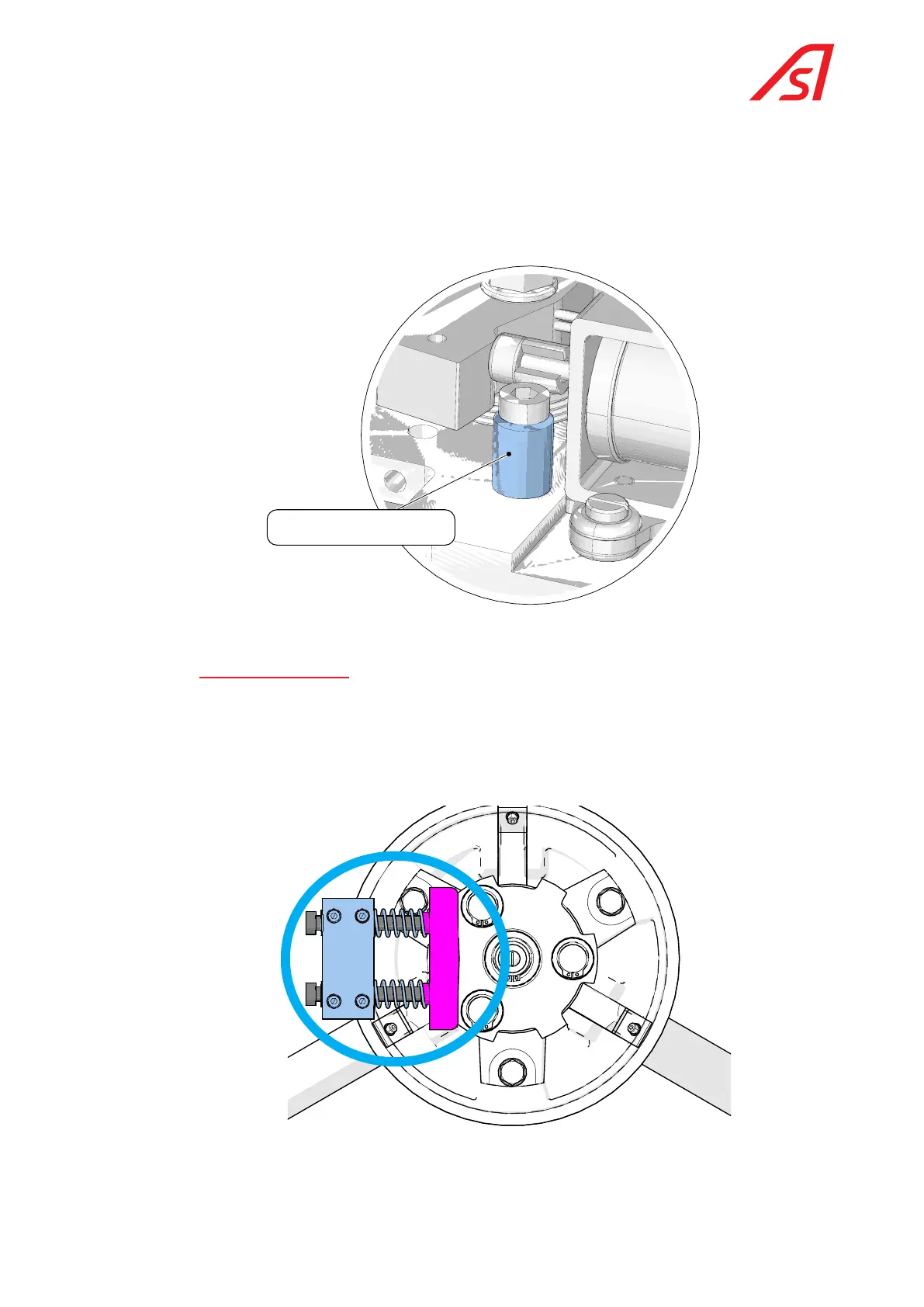
In order to reduce the noise level, each electro-magnet axis is equipped with a nylon spacer (see the figure below).
However, this spacer reduces the impact force during the unlocking operation, which can be a problem if the user exerts
significant pressure on the arm at this precise moment.
If this scenario occurs frequently, it is advisable to remove (unclip) these two spacers to increase the impact force on
the locks.
To gain access to the electro-magnet located at the back, remove the top plate of the mechanism, which is attached with
4 M10 hex-head bolts and 2 M6 upper bearing bolts.
Anti-noise spacer
Fig. 18 Anti-noise spacer on the axis of the electro-magnets
7.2.4. centring mechaniSm
The figure below illustrates the function of the centring mechanism: The plate is provided with three rollers, which
support the stop of the centring mechanism. The two springs located at the rear distribute the pressure on the
two rollers, which ensures perfect centring corresponding to the rest position (one of the three arms is perfectly
horizontal in order to block the passage).
This centring mechanism is not present on a motorised TriLane.
Fig. 19 View of the centring mechanism
 Loading...
