p. 30/46
TLxx-MT-EN-04
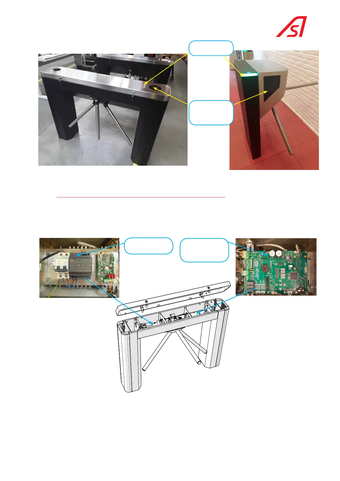
Functional
pictogram
Cover cutting and
Protection for reader
option
Fig. 27 Readers option
7.4. DESCRIPTION OF THE ELECTRONIC ASSEMBLY
Two circuit boards are incorporated in the central part of the TL2 casing: The power supply circuit board on the left side
and the electronics circuit board on the right side.
The 230 VAC power cable rises from the ground into the left foot of the turnstile. A hole is provided to connect the cable
to the main circuit breaker.
Power supply circuit
board
Electronic control
circuit board
Fig. 28 General overview of the electrical and electronic panels
On the TL1 version, the power cables are in the middle on the housing fixing points. The power supply circuit board, the
main circuit breaker (4.8) and the logic board are located inside the foot and the optional motor control board (4.4) is
located inside the top cover (See Fig. 29, page 31 and Fig. 30, page 31) .
 Loading...
