p. 32/46
TLxx-MT-EN-04
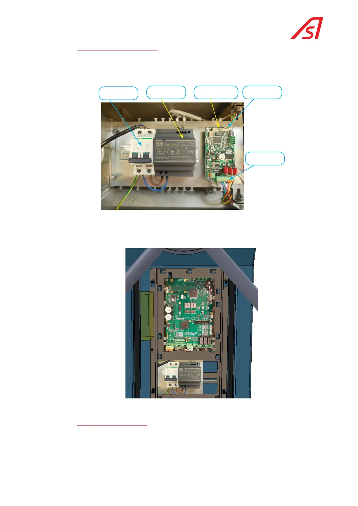
7.4.1. poWer Supply circuit board
The TL2 circuit board in the left holds the main circuit breaker and the 24 VDC power source. The motor electronics
ensuring the rotation of the turret.
It is recommended to cut the power before carrying out any work on the mechanical parts.
Motor circuit board
AS1636 (optional)
Power supply 24VDC
Main circuit breaker
CAN bus cable
Motor cable
Fig. 31 Power supply circuit board
The sub-assembly parts are identical for the TL1 version (circuit breaker, power supply and motor control board) but
the circuit breaker and the power supply are accessible removing the front panel and the AS1636 motor control board
(optional) is located inside the stainless steel cover.
Fig. 32 Power supply plate on TL1
7.4.2. electronic circuit board
The electronic circuit board contains a human machine interface (HMI) composed of 4 digits and a keyboard with 5
keys. The figure below shows the purpose of the main connectors. Some of them are reserved for the options available
on the TriLane (functional pictogram, detection cells, light strips, control card motorisation, Ethernet connection,
etc.,) and others are not used on the TriLane, because the AS1635 control electronics are also used in other products.
 Loading...
