p. 38/46
TLxx-MT-EN-04
Fig. 35 Fixing the dropping arm
9.2.3. replacing the angle SenSor aSSembly
The replacement of the sensor assembly does not pose any particular problems.
• Using the two locking keys, remove the central casing cover ("7.2.1. Removing the cover", page 23)
• Disconnect the power supply (main circuit breaker)
• Disconnect the connecting cable between the sensor and the AS1635
• Using an Allen key, remove the two mounting screws on the support and replace with the new sensor.
• A calibration operation is required at power-on. Refer to the unit test chapter in the AS1635 manual.
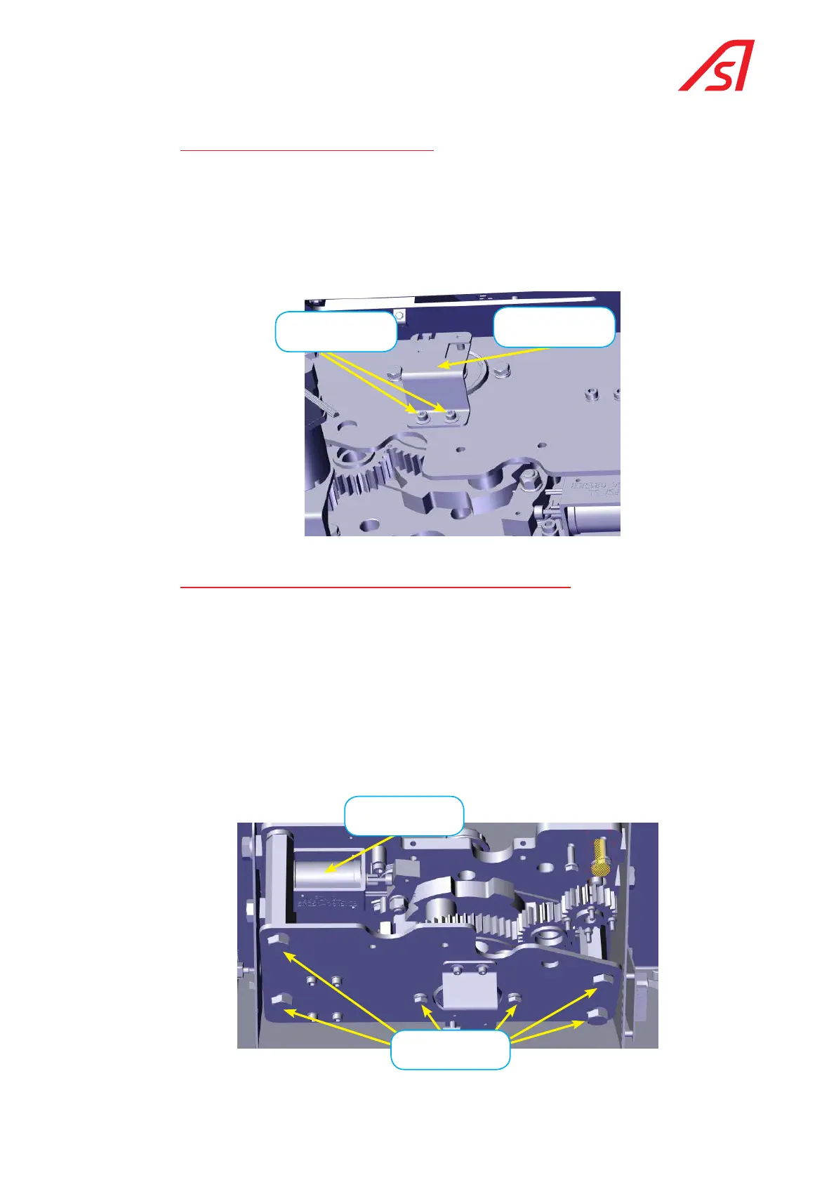
Allen fixing screw
Angle sensor plate
Fig. 36 Angle sensor
9.2.4. replacing or inverting the direction of an electro-magnet
The axes of the electro-magnets are symmetrical. By reversing the direction of the coil, which has an internal return
spring, it is therefore possible to go from configuration 4 (locked with power off) to configuration 5 (free with power
off). "4.3. Conventions", page 10.
• Remove the cover
• Disconnect the power supply (main circuit breaker)
• Remove the upper frame (6 bolts)
• Disconnect the electro-magnet cable.
• Remove the two M4 x 6 fixing screws
• Locate the new electro-magnet or reverse the position for a solution change between 4 and 5. In this case, it is
necessary to change the parameters in the control logic.
Fixing bold of the top
plate(6x)
Electro-magnet
 Loading...
