5 Guide For Connection
32 © Copyright Reserved Autonics Co., Ltd.
5.2 Input and Output connection
5.2.1 Input logic selection [no-voltage(NPN)/voltage(PNP)]
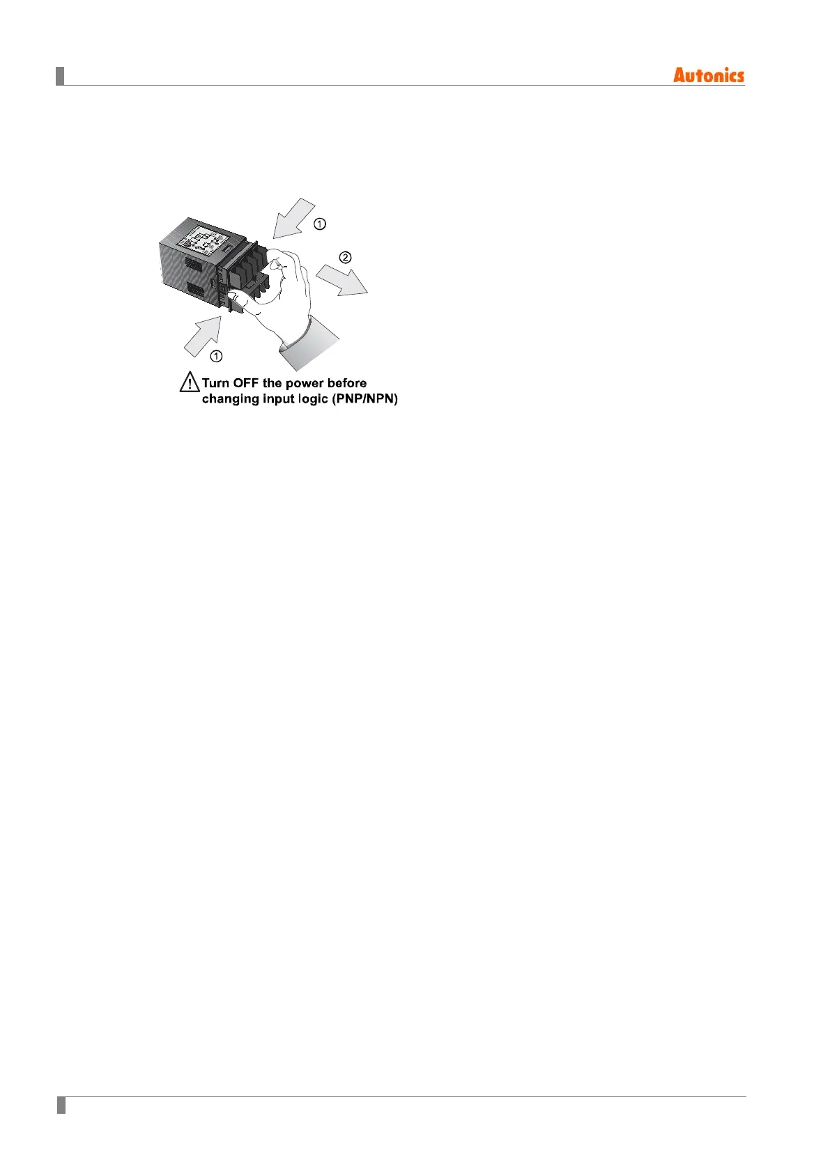
1. The power must be cut OFF.
2. Squeeze toward ① and pull toward ② as the figure. (CTS/CTY Series)
3. Select input logic by using input logic switch (SW1) inside Counter/Timer.
4. Push a case in the opposite direction of ②.
5. Then supply the power to counter/timer.
 Loading...