Technical description
Version: 2.1 ─── 39AS2000
Technical description
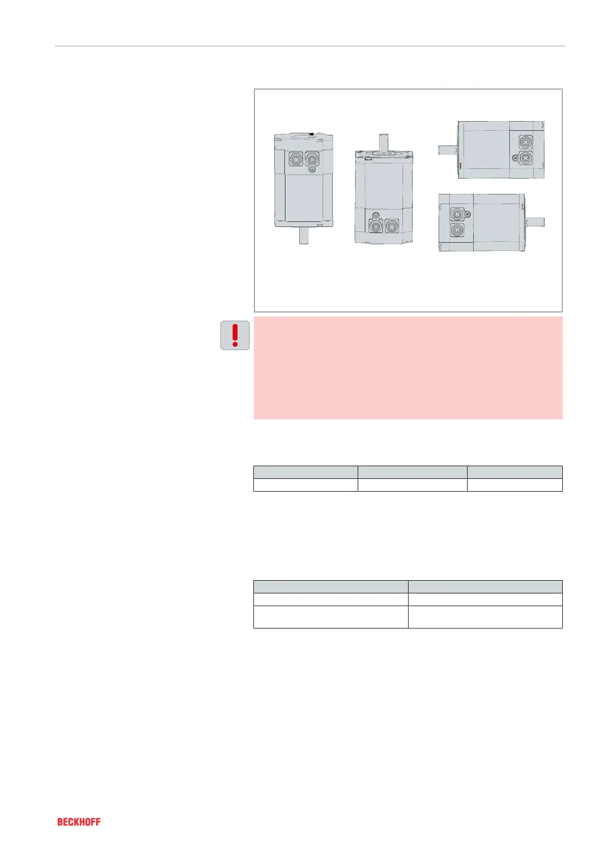
Mounting position
The standard installation position of the motors is the design IM B5
according to DIN 60034-7.
IM V18 (V18)
IM V1 (V1)
IM V19 (V19)
IM V3 (V3) IM B5 (B5)
IM B14 (B14)
Observe the maintenance intervals and mounting positions
Carry out maintenance at regular intervals.
In the vertically mounting position IM V3, liquid which has been left
on the flange for a longer period can penetrate the motor through
capillary action. In mounting position IM V1 liquid can escape.
If you do not observe the maintenance intervals, the motor may
overheat depending on the mounting position. Ingress and leak-
age of liquids may damage the motor.
Feedback
The following tables provide information about the resolution of the
motor feedback systems:
Feedback system Resolution Comment
Incremental encoders 1,024 increments AS20xx
Shaft end A
The A-end transmits the force via a backlash-free, force-locking con-
nection through a coupling and cylindrical shaft end according to
DIN 748-3 with front-sided center bore according to DIN 332-2. Al-
ternatively, forces can be transmitted via a frictional connection and
a feather key groove according to DIN 6885 / ISO 2491; only for
flange size 4 = N3.
Radial forces Axial forces
• Motors driven via pinion / toothed belt • Pinion or pulley mounted on the shaft
• Permissible values depend on the
speed
• For example, when operating angular
gear units
Preferred backlash-free coupling elements:
• Elastomer coupling, see chapter: "Mechanical installation",
[Page43]
 Loading...