8
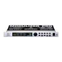
MODULIZER PRO DSP1224P
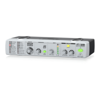
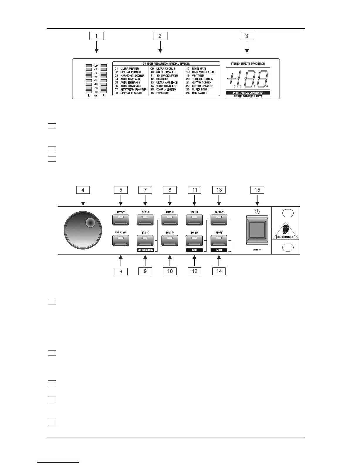
Fig. 1.2: Display section DSP1224P
1
The two LED chains read the input signal level indB, referenced to the internal digital maximum. Please
note that the nominal level of the MODULIZER PRO can be selected with the +4dBu/-10dBV switch
located on the back panel.
2
The effect table gives you an overview of the 24 different effect algorithms.
3
After power-up, the LED display reads the number of the preset last used. This clearly legible, 2½ digit
numeric display has plus/minus indicators to show that parameters are being incremented or decremented
in Edit mode.
Fig. 1.3: Function keys and jog wheel
4
With the jog wheel, a continuous rotary control, you can freely edit the selected parameters. Turn the
wheel clockwise to increase the values, or counterclockwise to reduce them.
As long as none of the edit functions to the right of the jog wheel has been selected, you can use the
wheel to select a program directly, which is shown by a dot lighting up in the display. While this dot is
on, you can select a program though its settings will not take immediate effect. When the jog wheel has
not been touched for one second, the LED in the display disappears and the program is loaded.
5
Use the EFFECT key to directly select one of the 24 basic effect algorithms with the jog wheel.
+ Whenever a new algorithm is selected, all parameters are reset to default values.
6
The VARIATION key allows you to select the most important parameter of each algorithm, for example
LFO speed for algorithm 1, i.e. a phaser then can be modified with the jog wheel.
7
In each preset you can edit at least three and mostly four parameters in addition to the preset
VARIATION. Use the EDITA key to select the first parameter. The exact parameter assignment can be
seen from the parameter list printed on the enclosure top and in the appendix.
8
Use the EDITB key to select another parameter which is to be altered.
1. INTRODUCTION
 Loading...