68
DISASSEMBLY PROCEDURES
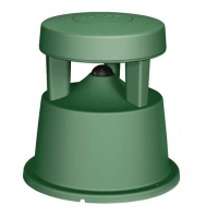
11.3 Disconnect the ground connection wire.
Retain the nut for re-use. Disconnect the
wiring harness at J3.
11.4 Disconnect the AC wiring harness at J1.
Disconnect the three wire harnesses at J4,
J5 and J7.
Note: J4 and J5 are located across the PCB
assembly from each other. The J4 connector
is red and the J5 connector is white. Lift off
the SMPS / Amp assembly.
Important Note: The SMPS / Amplifier PCB
assembly is a densely packed assembly with
many components secured with glue to
prevent vibration and buzzing. Component
level repair is NOT recommended for this
assembly.
F1 Subwoofer
Important Note: The top, bottom and rear
handles and their inserts are not replaceable
for safety reasons. Do not attempt to remove
them. They are not stocked as repair parts.
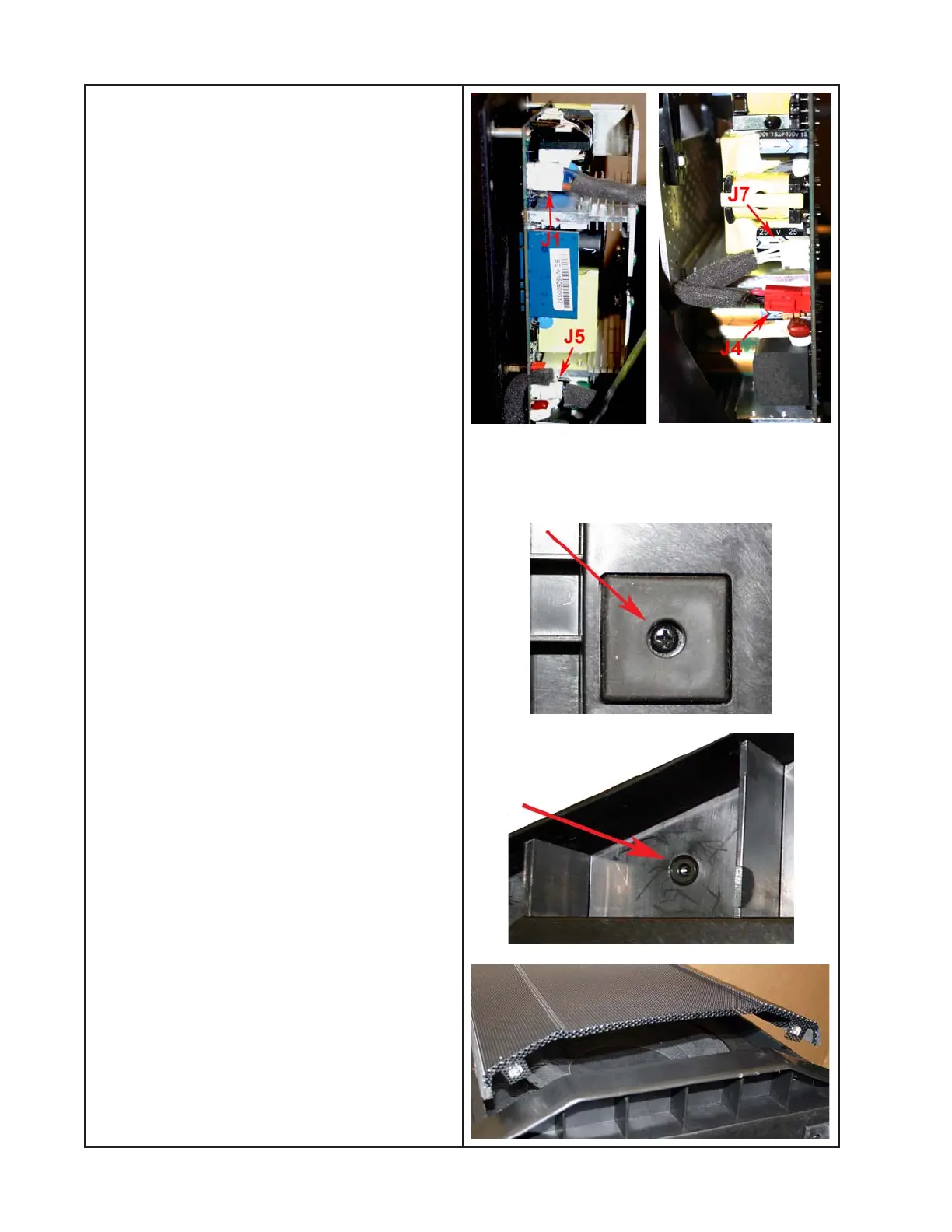
1. Foot Removal
1.1 Remove the one screw that secures the
foot to the loudspeaker enclosure.
1.2 Lift off the foot.
2. Grille Removal
2.1 At the bottom of the loudspeaker, below
the cabinet edge, remove the two hex head
T15 size screws that secure the grille to the
loudspeaker enclosure.
 Loading...