72
TEST PROCEDURES
F1 Model 812 Loudspeaker
Equipment Required:
• Balanced audio signal generator
• Balanced input audio signal
analyzer / dB meter
• Switching Amplifier filter,
AP AUX-0025 or equivalent
• MP3 player for pink noise file
• Balanced XLR male cable
• Balanced XLR female cable
• Balanced 1/4”’ TRS cable
• RCA cable
• AC line cord
• 2 - 4 ohm, 250 Watt load
resistors
1. Power-up Test
1.1 Connect the unit under test to
AC mains.
1.2 Turn on the AC power switch.
Verify that there is no loud turn-on
pop. Verify that the Power/Fault
LED is lit BLUE. If it is RED, there
is a failure and the unit will need to
be troubleshot and repaired.
1.3 Place the Front LED switch to the POWER position. Verify that the front LED located at the
lower right front of the speaker is lit blue.
1.4 Change the Front LED switch to the OFF position. Verify that the front LED is now OFF.
1.5 Change the Front LED switch to the LIMIT position. Leave it in this position for the following
tests. You will be checking it for proper operation during these tests.
1.6 Turn the AC power switch OFF. Verify that there is no loud off-pop.
Input / Output - DSP PCB Tests
The following tests will check the performance of the Input / Output - DSP PCB assembly.
CAUTION: You MUST NOT test this PCB assembly while it is still connected to the
SMPS / Amplifier PCB assembly. Doing so could cause hearing damage due to high SPL
output levels from the speaker.
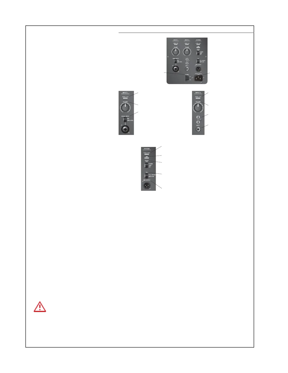
F1 Model 812 Control Panel
POWER/FAULT:
• Blue = power on.
• Red = fault condition.
LIMIT:
• Red = system limiting.
Front LED:
• POWER enables front LED to indicate power status.
• LIMIT engages a limiting display on the front LED.
• OFF turns o the front LED.
EQ:
• FULL RANGE allows the loudspeaker to function without high-pass
filtering.
• WITH SUB engages a high-pass filter when using the loudspeaker
with the F1 subwoofer.
LINE OUTPUT:
• Balanced XLR line output provides a mix of input 1 and 2, post input
faders. Can be used to daisy chain speakers together.
SIGNAL/CLIP: Displays the input
signal status in color.
• Green = signal present.
• Red = signal clipping.
VOLUME: Adjusts channel volume.
SIGNAL INPUT:
Selector switch sets input sensitivity
for input type.
Connector accepts XLR connector or
¼" phone plug.
• MIC selects sensitivity for mic
inputs (dynamic or self-powered
mics only) – use only when a mic is
connected directly to the input.
• LINE selects sensitivity for line-
level inputs, for example, from a
mixer or DJ controller.
RCA connectors : Analog stereo input for
audio sources such as DVD players, VCR
players, video game consoles, DJ mixers,
keyboards and other instruments.
¼" phone connector : Provides analog
input for guitars and other instruments.
Accepts TRS balanced or TS unbalanced
cables.
SIGNAL/CLIP: Displays the input
signal status in color.
• Green = signal present.
• Red = signal clipping.
VOLUME: Adjusts channel volume.
POWER: AC
power on/o
AC power
input
 Loading...