2
CONTENTS
SAFETY INFORMATION ...........................................................................................................................4
ELECTROSTATIC DISCHARGE SENSITIVE (ESDS) DEVICE HANDLING ............................................5
WARRANTY................................................................................................................................................5
PART LIST NOTES ....................................................................................................................................5
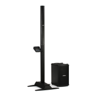
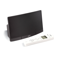
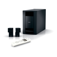
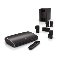
PRODUCT DESCRIPTION.......................................................................................................................6-8
PACKAGING PART LIST ...........................................................................................................................9
Figure 1. Packaging Exploded View ........................................................................................................9
MAIN ASSEMBLY LIST, L1 Pro8 Power Stand..................................................................................10-11
Figure 2. L1 Pro8 Power Stand Exploded View .....................................................................................12
MAIN ASSEMBLY LIST, L1 Pro8 IO Panel Assy................................................................................13-14
Figure 3. L1 Pro8 IO Panel Assy Exploded View ...................................................................................15
MAIN ASSEMBLY LIST, L1 Pro8 Array Speaker.....................................................................................16
Figure 4. L1 Pro8 Array Speaker Exploded View ...................................................................................17
MAIN ASSEMBLY LIST, L1 Pro8 Extension............................................................................................18
Figure 5. L1 Pro8 Extension Exploded View ..........................................................................................18
MAIN-I/O PCB PART LIST...................................................................................................................19-27
POWER-AMP PCB PART LIST...........................................................................................................28-32
VOLUME PCB PART LIST........................................................................................................................33
DISASSEMBLY PROCEDURE............................................................................................................34-40
Figure 6. PC Sheets Location .................................................................................................................34
Figure 7. PC Sheets Removal ................................................................................................................34
Figure 8. Enclosure Bottom Screws Removal .........................................................................................34
Figure 9. Enclosure Bottom Removal .....................................................................................................35
Figure 10. Grille Removal .......................................................................................................................35
Figure 11. I/O Panel Assy Screws Removal ............................................................................................35
Figure 12. Incline the Power Stand .........................................................................................................36
Figure 13. Main-IO Board & Power-Amp Board Cables .........................................................................36
Figure 14. Antenna Board Screws Removal ..........................................................................................36
Figure 15. Power-Amp Board Screws Removal ......................................................................................37
Figure 16. Heat Sink Thermal Grease......................................................................................................37
Figure 17. Shield Cover Screws Removal 1.............................................................................................37
Figure 18. Shield Cover Screws Removal 2.............................................................................................37
Figure 19. White Glue Removal ..............................................................................................................38
Figure 20. Fire Box & Main-IO Board Screws Removal...........................................................................38
Figure 21. 4 Jacks and Jack Socket Nut Removal...................................................................................38
Figure 22. Volume Board Screws Removal.............................................................................................39
Figure 23. Woofer Screws Removal........................................................................................................39
Figure 24. Press the White Fastener........................................................................................................39
Figure 25. Both ends of Endcaps Screws Removal.................................................................................39
Figure 26. Lower Endcap Removal..........................................................................................................40
Figure 27. Array Grille Removal...............................................................................................................40
Figure 28. Gasket Material Locations......................................................................................................40
Figure 29. Driver Screws & Cable Removal............................................................................................40
Title Page

 Loading...