23
DISASSEMBLY PROCEDURE CONTINUED
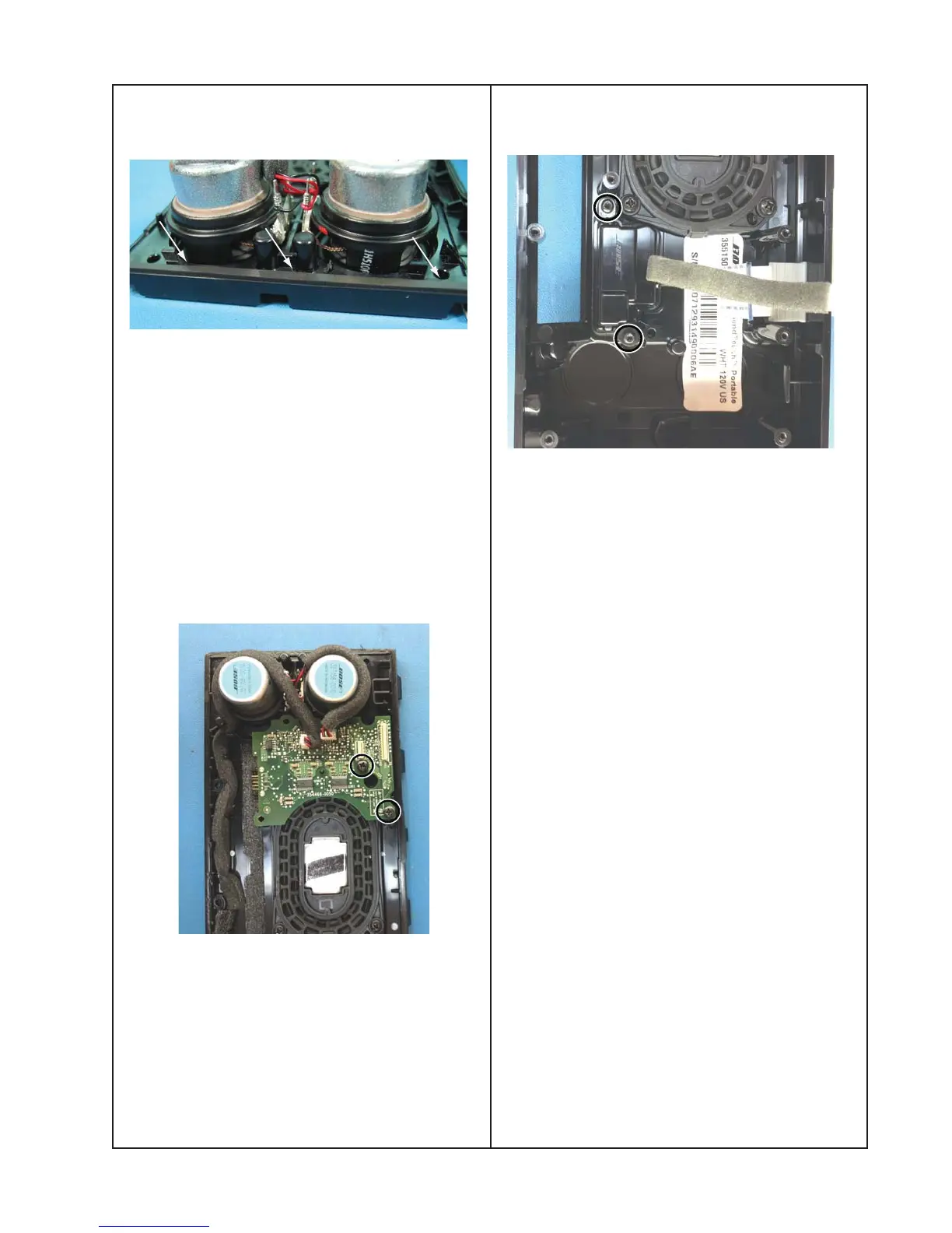
9. I/O PCB Removal
9.1 Remove the two screws securing the
I/O PCB.
Acoustic Enclosure disassembly (contin-
ued)
7.1 Use the gasket strip kit (part number
349600-001S) to replace the gasket. See
above.
Make sure the gasket strips are not placed
beyond the outside of the assembly. This
would result in a cosmetic defect.
Once the system is fully assembled, an air
leak test must be performed to confirm the
acoustic seal is correct.
8. Amplifier PCB Removal
8.1 Remove the two cables connecting the
four driver assemblies.
8.2 Remove the two screws holding the
Amplifier board to the front enclosure.
 Loading...