#
/
-
2ALLENTAM6ELOCITÍ
-AX-AX -ED -IN -IN
$)3
/.
.
-
04 & &#
&!
.
,
,
,4
%
#
#
'.$4828
9
8
710
11
1
2
12 133
6
5
4
14
18
16
15
17
p.
12 - Manual code:
FA01036-EN v.
- 01/2018 - © Came S.p.A. - The manual's contents may be edited at any time without notice.
FUSE TABLE ZL38
- Line 3,15 A-F
- Card
630 mA-F
- Gearmotor
10 A-F
- Accessories
2 A-F
ELECTRICAL CONNECTIONS AND PROGRAMMING
⚠
Warning! Before working on the control panel, cut off the main current supply and, if present, remove any batteries.
Power supply to control panel and control devices: 24 V AC/DC.
The features are set using the DIP switches, the adjustments using the trimmer.
All connections are quick-fuse protected.
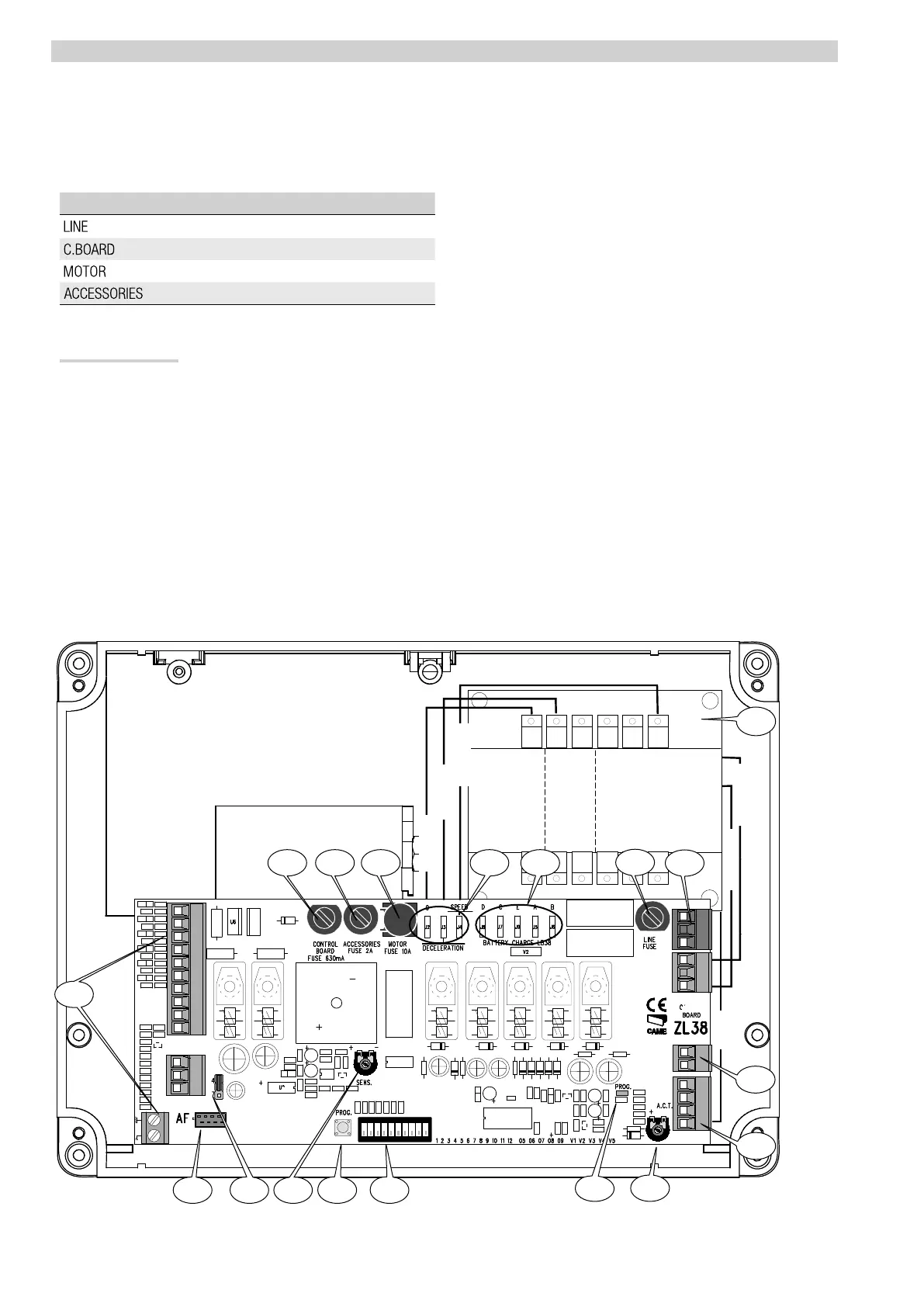
Description of parts
1. Accessories fuse
2. Line fuse
3. Control board fuse
4. Motor fuse
5. Terminals for control and safety devices
6. AF card connector
7. SENS trimmer
8. ACT Trimmer
9. DIP-SWITCH
10. Programming button
11. Programming warning LED
12. Speed and slow-down adjusting connectors
13. Battery charger (LB38) connectors
14. Command type selection jumper
15. Transformer
16. Power supply terminals
17. Gearmotor terminal
18. Limit switch terminals
White
Red
Black
Brown
Blue
Brown
 Loading...