C
A
M
E
R
%##
,
.
28
48 '.$
28
48 '.$
,
.
%##
ON
2
1 345678910
N
M
PT F FC
FA
N
L
L27
L1T
GNDTXRX
E
+10
-11
1
2
3
5
7
C1
C5
C
A
M
E
R
ON
2
1 345678910
N
M
PT F FC
FA
N
L
L27
L1T
E
+10
-11
1
2
3
5
7
C1
C5
GNDTXRX
7 ON
p.
20 - Manual code:
FA01036-EN v.
- 01/2018 - © Came S.p.A. - The manual's contents may be edited at any time without notice.
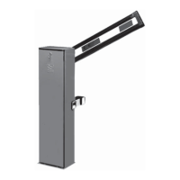
CONTROL BOARD MASTER
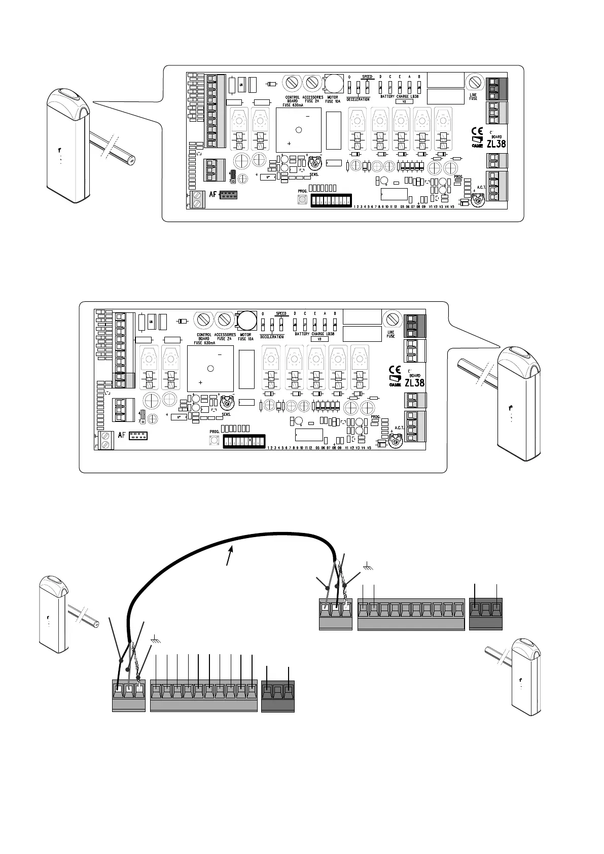
CONTROL BOARD
SLAVE
On the SLAVE barrier's control board, connect the power supply to L-N, the fl ashing light on 10-E, set DIP switch 7 to ON and adjust the
travel and slow-down speeds just like on the MASTER barrier.
On the MASTER barrier's electronic board, make the necessary electrical connections, activate the radio control, program the functions
and settings.
Connect the two control boards using terminals RX-TX-GND as shown in the fi gure.
Screened cable
2402C 22AWG
Red
Black
Red
Black
MASTER
SLAVE
 Loading...