FCP manual
Code +030220391 – rel 1.2 25/03/08
14
6. Description of the functions
6.1 Control modes
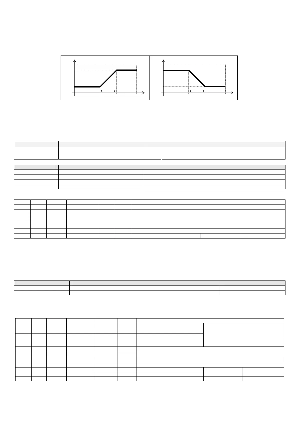
The following operating modes can be set:
Direct an increase in the value measured by the probes increases the value of the output;
Reverse an increase in the value measured by the probes decreases the value of the output.
OUT
DIRECT
max
min
setp
100%
100%
dif
OUT
REVERSE
max
min
setp
100%
100%
dif
Fig. 6.a
All the functions and observations applied in Direct mode, are valid symmetrically in Reverse mode. Direct mode is set by default (alternatively the selection can be
associated with dipswitch 4).
The values of the set point, differential, minimum and maximum output can be set by dipswitch or by setting the parameters.
If the minimum output set is greater than the maximum output, the value is limited internally to maximum output.
The value of the differential is internally limited so as to in any case ensure the maximum output value set is reached (for example if SET+DIF > 100%, DIF is limited
to 100%-SET).
Dipswitch Function
OFF: setting by parameters Dip1 Select device setting mode
ON: setting by trimmer
Table 6.a.a
Trimmer Function
SET Set the set point 0 – 100%
DIF Set the differential 0 – 20%
MIN Set the minimum output 0 – 100%
MAX Set the maximum output 0 – 100%
Table 6.a.b
Associated parameters
par. Spv Modb range def uom description
STP1 I4 104 0 to 100 50 1% Set point (Setpoint1)
STP2 I5 105 0 to 100 50 1% Setpoint2
STPM I6 106 0 to 100 0 1% Setpoint1 memory set by trimmer
DIFF I7 107 0 to 100 10 1% Differential
MIN I8 108 0 to MAX 30 1% Minimum output
MAX I9 109 MIN to 100 100 1% Maximum output
EREV D1 1 0/1 0 1 Direct/Reverse mode 0=direct 1=reverse
Table 6.a.c
6.2 Configuring the probes and selecting the range of measurement
The values of the set point and differential are always internally expressed as a % of the range of measurement used, so as to be able to manage different types of
probes at the same time. For ratiometric pressure probes, the range of measurement is the rated value of the probe.
For temperature probes, the range of measurement can be set by parameter and can be limited compared to the maximum rated value of the probes used, so as to
improve the resolution of control.
type of NTC probe maximum range settable by parameter default range
NTC 10kΩ @25°C -50 to +90 °C -10 to + 90 °C
NTC 50kΩ @25°C 0 to +120 °C +20 to +120 °C
Table 6.a.d
The default range, for both types of probes, has an interval of 100°C so as to simplify the conversion of the set point and above all the differential into a percentage.
The values measured by the probes are digitally filtered to attenuate any external disturbance. The filter can be set by parameter.
Associated parameters
par. Spv Modb range def uom description
PB1M I17 117 0 to 3 2 1 Type of probe B1
0 = NTC-10kΩ
3 = 0/10V
PB2M I18 118 0 to 2 2 1 Type of probe B2
1 = NTC-50kΩ
PB3M I19 119 0 to 1 0 1 Type of probe B3 2 = 0/5V ratiometric
FILT I23 123 0 to 13 6 1 Probe filter 0=minimum filter
13=maximum filter
T0L A2 2 -50.0 to T0H -10.0 0.1°C
Lower limit of meas. range NTC-10k
Ω corresponding to 0%
T0H A3 3 T0L to +90.0 +90.0 0.1°C
Upper limit of meas. range NTC-10kΩ corresponding to 100%
T1L A4 4 0.0 to T1H +20.0 0.1°C
Lower limit of meas. range NTC-50kΩ corresponding to 0%
T1H A5 5 T1L to +120.0 +120.0 0.1°C
Upper limit of meas. range NTC-50kΩ corresponding to 100%
PB1E D6 6 0/1 1 1 Enable probe B1 0=disabled 1=enabled
PB2E D7 7 0/1 1 1 Enable probe B2 0=disabled 1=enabled
PB3E D8 8 0/1 0 1 Enable probe B3 0=disabled 1=enabled
Table 6.a.e

 Loading...


