FCP manual
Code +030220391 – rel 1.2 25/03/08
19
Associated parameters
par. Spv Modb range def uom description
OUTV I37 137 0 to 100 R/W 1% reading/Override output
EOVR D15 15 0/1 0 1 Enable override output 0=disabled 1=enabled
Table 6.b.b
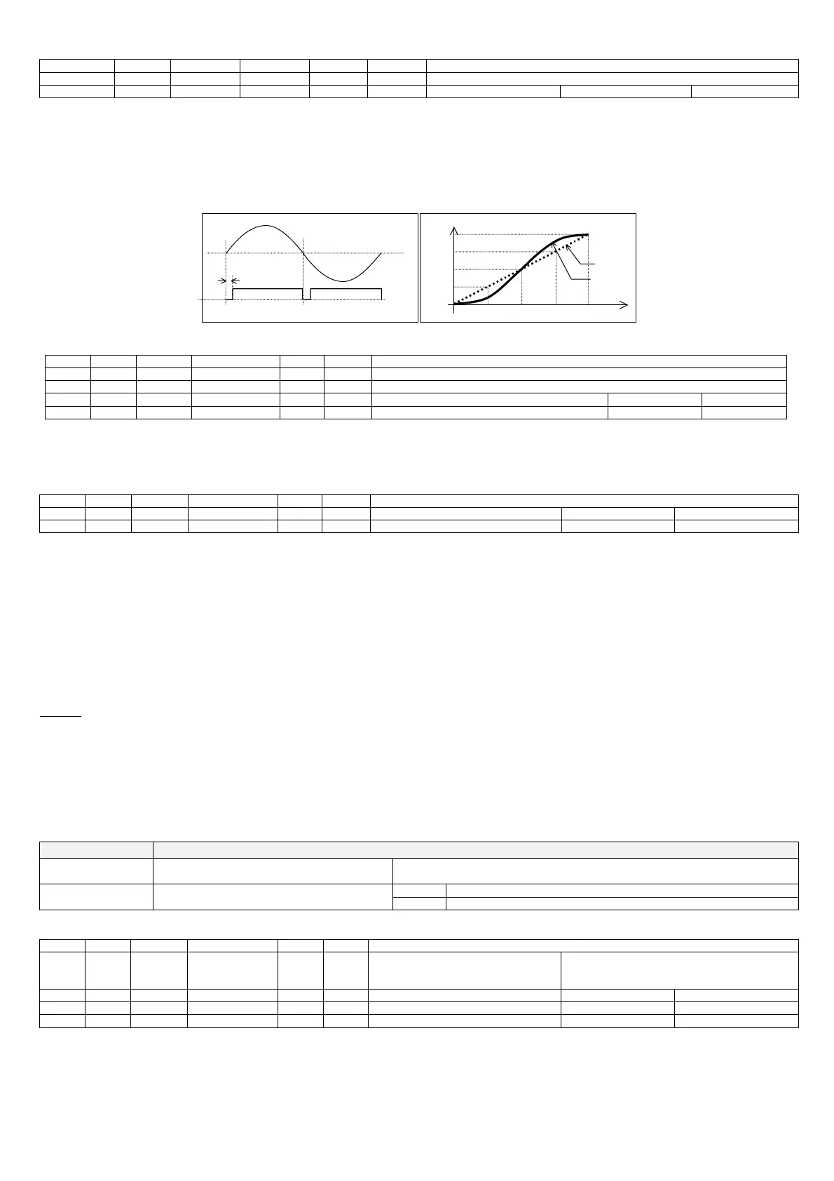
6.12 Phase control modes
By default control is based on short impulses (around 3ms). Alternatively, control can be enabled for long impulses (control is maintained until the end of the half
period).
The displacement of the phase control function can also be changed with reference to the zero-crossing of the mains voltage, so as to adapt it to the cos-fi of the fan.
The linearisation of the output RMS voltage can also be enabled, rather than use the traditional sinusoidal relationship between phase control and voltage.
Finally, the instant variation in the output can be limited so as to improve the behaviour of the fan, especially when starting from standstill.
Phase delay @ 100% output
0%
oltage(RMS) outpu
100%
OUT
100%
ELIN on
ELIN off
Fig. 6.h
Associated parameters
par. Spv Modb range def uom description
DLPL I21 121 0 to 100 10 1% Phase displacement (100% -> 90°)
STEP I24 124 0 to 10 1 1sec Output ramp (minimum time for variation from 0% to 100%)
ELIN D9 9 0/1 1 1 Enable output linearisation 0=disabled 1=enabled
ELPL D10 10 0/1 0 1 Enable long impulse phase control 0=disabled 1=enabled
Table 6.b.c
6.13 Automatic adaptation to the mains frequency
At power-on the mains frequency is measured so as to adapt operation to 50Hz or 60Hz
The status of the mains frequency reading is accessible via serial line.
par. Spv Modb range def uom description
OKHZ D26 26 0/1 R 1 mains frequency reading status 0=not ok 1=ok
STHZ D27 27 0/1 R 1 mains frequency 0=50Hz 1=60Hz
Table 6.b.d
6.14 Alarm situations and alarm management
Alarm status is activated in the event of:
- activation of the thermal protector (or in any case, the opening of the contact connected to the digital input configured as the alarm input);
- fault on probes B1 or B2;
- error reading/writing the parameters saved in non-volatile memory (EEPROM).
The alarm status is signalled by the red LED, depending on the causes, in order of priority:
on steady parameter alarm
1 impulse probe alarm
2 impulses digital input open alarm
In the event of more than one alarm at the same time, the signal with the highest priority is shown.
Warning:
if digital input ID1 is set as normally open, the alarm is active when ID1 is closed.
The probe fault alarm is generated if the probe is disconnected or short-circuited. Only the probes enabled by parameter and/or dipswitch are managed (probe B1 is
enabled by default, while probe B2 can be enabled by dipswitch).
In alarm status, the controller output provides one of three possible voltage values, with reference to the mains voltage, which can be set by parameter: 0%; 50%;
100% (default).
Normal operation is restored automatically as soon as the alarm situation is resolved. In the event of alarms due to errors when reading/writing the parameters, the
parameters take the default values. The alarm is reset only when a correct parameter copy operation is performed using the key or the parameters are written from
the supervisor.
If the alarm persists, the EEPROM is faulty.
Dipswitch Function
OFF: external alarm (thermal protection activated) Dip2 Select digital input function
ON: set point selection (enable double set point)
OFF: single circuit (probe B1 only) Dip3 Enable two circuits
ON: two circuits (both probes B1 and B2)
Table 6.b.e
Associated parameters
par. Spv Modb range def uom description
ALMO I11 111 0 to 2 2 1 Output in alarm status
0=0%
1=50%
2=100%
PB1E D6 6 0/1 1 1 Enable probe B1 0=disabled 1=enabled
PB2E D7 7 0/1 1 1 Enable probe B2 0=disabled 1=enabled
MOID D11 11 0/1 0 1 Operating logic of digital input ID1 0=normally closed 1=normally open
Table 6.b.f

 Loading...


