FCP manual
Code +030220391 – rel 1.2 25/03/08
18
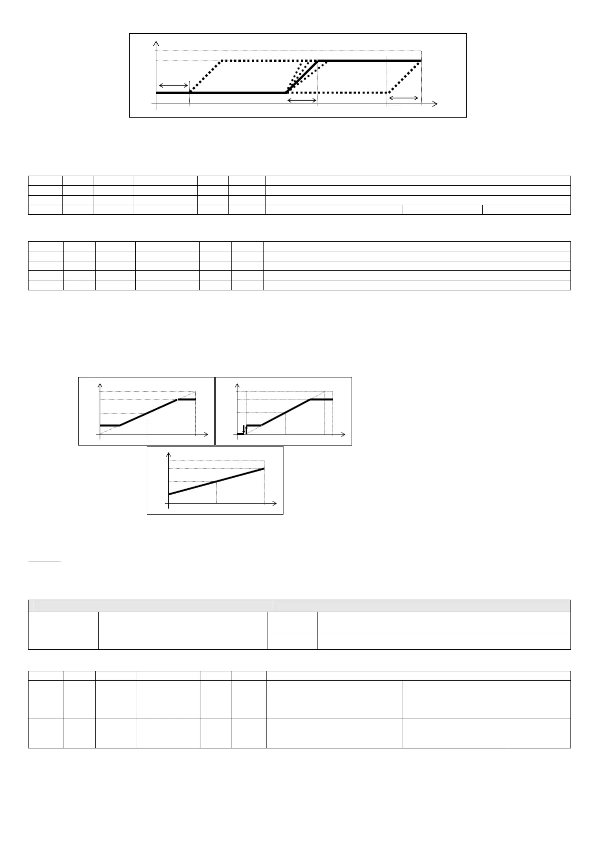
OUT
max
min
setp
MIN
100%
diff
diff
MAX
100%
diff
MAX
setp
MAX
Fig. 6.f
In this regard, it is good practice for the operating range of the probes to allow the set point to be set away from the extremes, by a value greater than the maximum
differential envisaged. For example, if the differential being set does not exceed 20%, set point should not be outside of the interval 20% to 80%.
Associated parameters
par. Spv Modb range def uom description
INTT I15 115 1 to 30 10 1min Integral time for PI control
AWUP I16 116 0 to 100 50 1% Limitation of the integral action (antiwind-up)
EPIR D5 5 0/1 0 1 Enable PI control (Integral) 0=disabled 1=enabled
Table 6.a.u
To simplify the fine-tuning of the parameters, some variables that are available that describe the status of control in terms of the various components:
ERRR I38 138 -255 to 255 R 1 control error (255 = 100%)
OUTP I39 139 -255 to 255 R 1 proportional component (255 = 100%)
OUTI I40 140 -255 to 255 R 1 integral component (255 = 100%)
OUTM I41 141 0 to 255 R 1 minimum component (255 = 100%)
OUTR I42 142 0 to 255 R 1 control output (255 = 100%)
Table 6.a.v
The values are expressed with the maximum resolution possible (8 bits plus sign), therefore the value 255 corresponds to 100%.
6.10 Slave mode function
The control algorithm is disabled and the output of the controller is directly proportional to input probe B1, in one of the three modes that can be selected by parameter
(alternatively, its status can be set using dipswitch 4).
Fig. 6.g
Normally the control signal is supplied by an external controller using the 0/10V standard, however any signal compatible with those allowed for probe input B1 can
be used, setting the input accordingly.
Warning:
if the control signal applied to probe input B1 is 0/10V, the setting must be made by manually moving a jumper.
With probe input B1 set for a 0/10V signal, the fault probe can no longer be managed. When the function is active, probe input B2 is not managed, irrespective of its
setting.
The function is disabled by default.
Jumper
JA on
JB off
input for pressure/temperature probes JA, JB 0/10V input configuration (probe input B1 only)
JA off
JB on
0/10V input
Table 6.a.z
Associated parameters
par. Spv Modb range def uom description
MODE I10 110 0 to 3 0 1 Control mode 0=standard control;
1=slave mode 1
2=slave mode 2
3=slave mode 3
0 = NTC-10kΩ
3 = 0/10V
1 = NTC-50kΩ
PB1M I17 117 0 to 3 2 1 Type of probe B1
2 = ratiometric 0/5V
Table 6.b.a
6.11 Overriding the output
The output can forced to the desired value required at any time via serial line, irrespective of the value calculated by the controller. This function is temporary and is
not saved; it is disabled automatically 10 seconds after the termination of the serial connection.
OUT
SLAVE Mode 1
max
min
100%
100%
OUT
SLAVE Mode 2
max
min
100%
100%
5% 95%
OUT
SLAVE Mode 3
max
min
100%
100%
50%
50%
50%
50%
50%
(max+min)/2

 Loading...


