FCP manual
Code +030220391 – rel 1.2 25/03/08
33
8. Tables of alarms and signals
8.1 Alarms
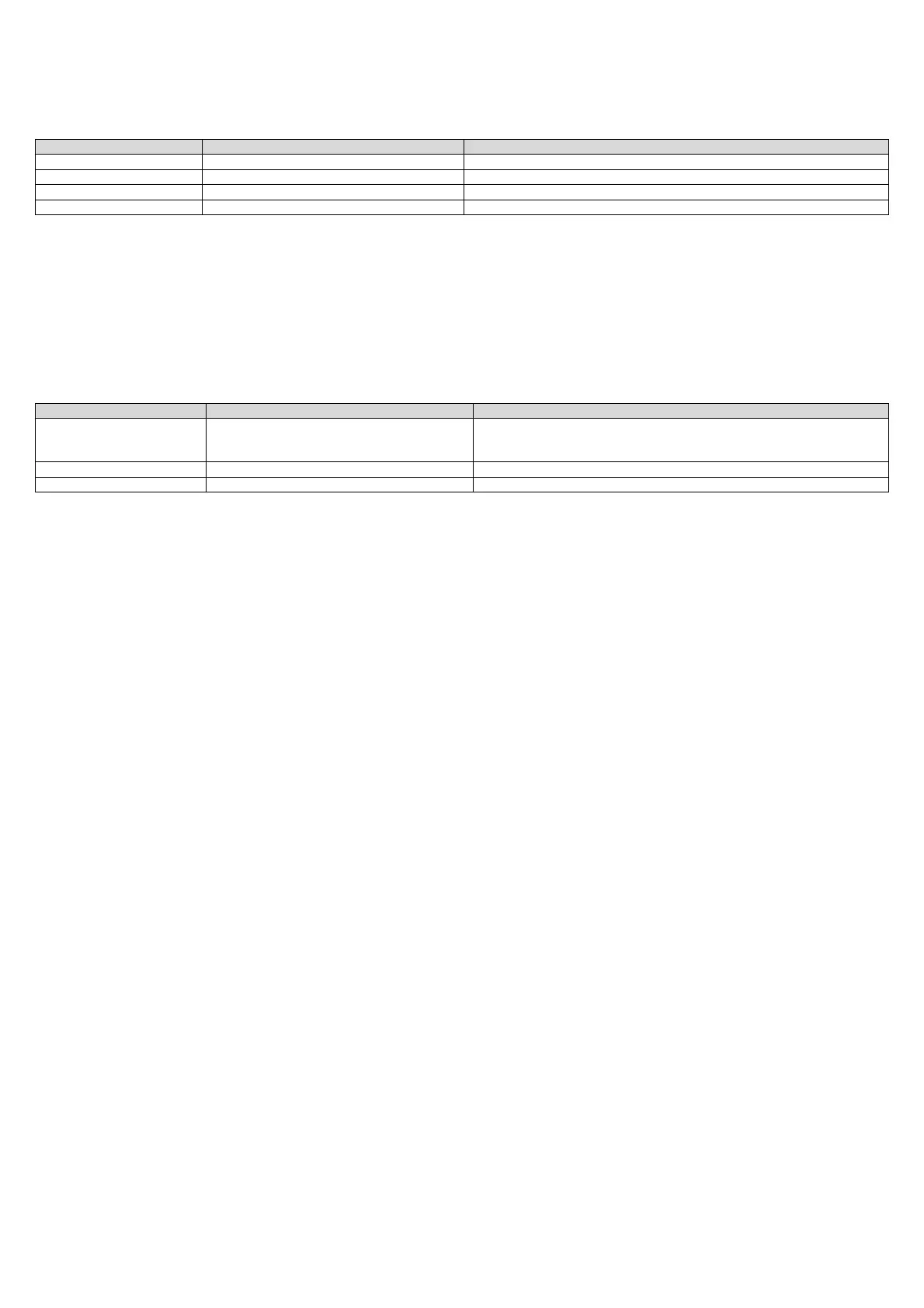
The alarm status is indicated by the red LED
status of the red LED description possible causes of the alarm
off no alarm
on parameter error alarm non-volatile memory error (EEPROM)
flashing 1 impulse probe B1 or B2 faulty alarm probes disconnected or short-circuited
flashing 2 impulses external alarm opening of the contact associated with the digital input
Table 8.a
The probe fault alarms are only detected for the probes that are enabled.
If there are multiple alarms activated at the same time, the first in order shown in the table is signalled.
The active alarm status forces the output to the value defined by the ALMO parameter.
The alarm status is available via serial line.
8.2 Signals
Power is signalled by the green LED.
The status of the serial connection is signalled by the yellow LED.
status of the yellow LED description possible causes
off connection deactivated cable disconnected
supervisor off-line
protocol not supported
flashing data reception data reception with correct protocol
on connection active the connection is active, but no data is being received.
Table 8.b
The serial connection is automatically deactivated 10 seconds after the last valid data is received.

 Loading...


