14
2
1
1
1
11 1
1
1
2
2
222
2
2
3
3
4
5
6
6
7
7
8 8
9
10
11
12
10
11
12
13
15
16
17
14
2
1
3
4
5
6
7
8
9
10
11
12
13
14
ENGLISH
µC
2
SE - +030220426 - rel. 2.0 - 03.08.2009
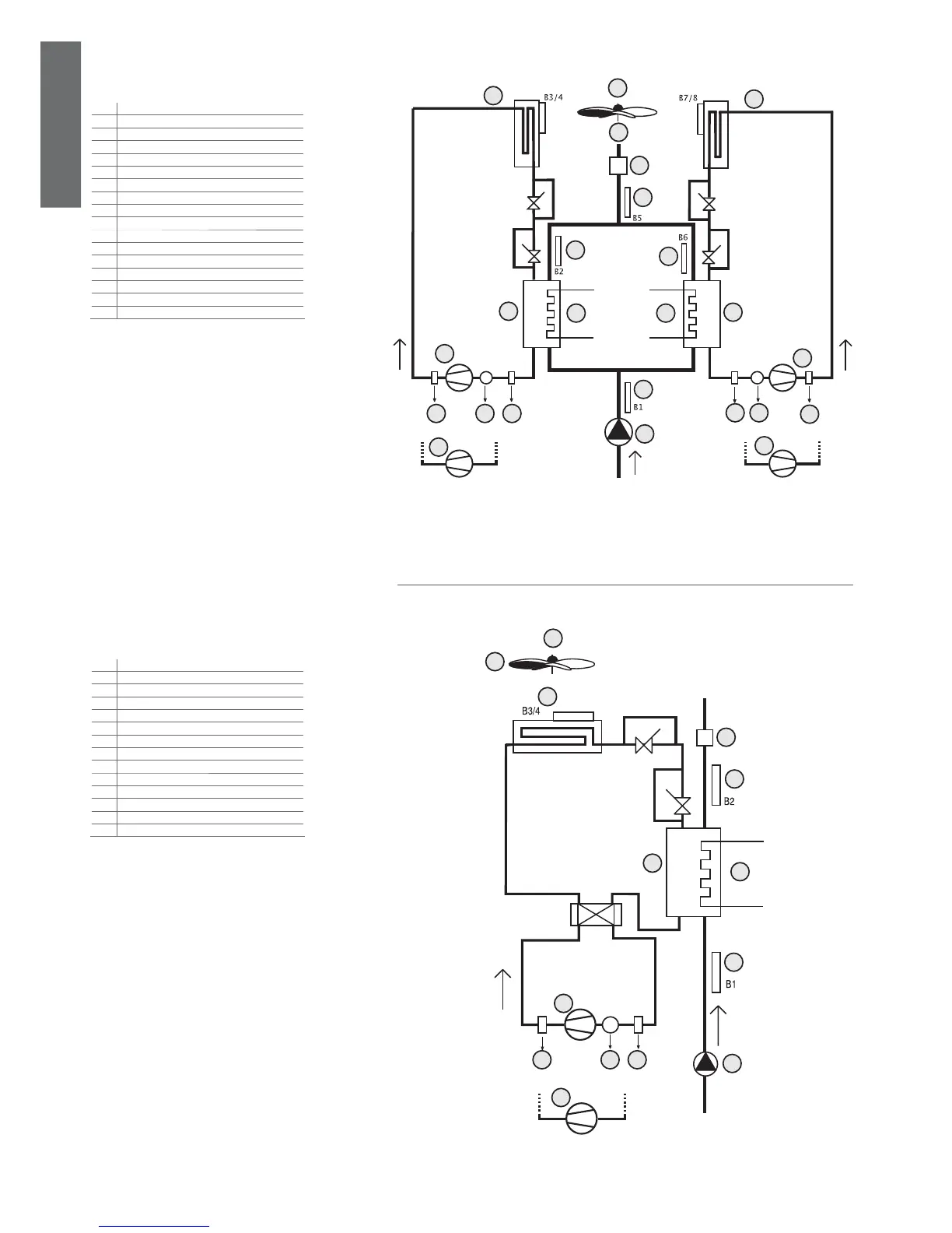
Fig. 3.c.c
Fig. 3.d.a
3.3.2 two circuits, 1 condenser fan circuit
3.4 AIR/WATER heat pump
3.4.1 Single circuit
Key:
1 condenser fan overload
2 fan
3 condenser probe 1 and 2
4 fl ow switch
5 outlet temperature probe
6 evaporator 1 and 2
7 outlet evaporator probe 1 and 2
8 antifreeze heater 1 and 2
9 compressor 1
10 high pressure 1 and 2
11 compressor overload 1 and 2
12 low pressure 1and 2
13 inlet evaporator probe
14 compressor 2
15 water pump
16 compressor 3
17 compressor 4
Key:
1 condenser fan overload
2 fan
3 sonda condensatore
4 fl ow switch
5 outlet evaporator probe
6 evaporator
7 antifreeze heater
8 inlet evaporator probe
9 compressor 1
10 high pressure
11 compressor overload
12 low pressure
13 water pump
14 compressor 2
 Loading...


