26
ENGLISH
µC
2
SE - +030220426 - rel. 2.0 - 03.08.2009
4.3 Parameter tables
The following tables show of the parameters divided by type/family (e. g. compressor, probes, fans etc.).
• Key to the parameter tables
Level (default)
S= super user
F= factory
D= direct
Visibility:
The visibility of some groups depends on the type of controller and the value of the parameters.
D= defrost (if D01=1)
F= fan (if F01=1)
L= low noise (if F15=1-3)
N= NTC probe (if /04-/08=2)
P= pressure (if /04-/08=3)
V= driver (if H08 =1, 3, 4)
X= expansion (if H08=2, 3, 4)
M= pump down (if D17=1)
W= watch (if the clock board is fi tted)
- = always present
Supervisor variables:
R/W = supervisor read/write parameter
R= supervisor read-only parameter
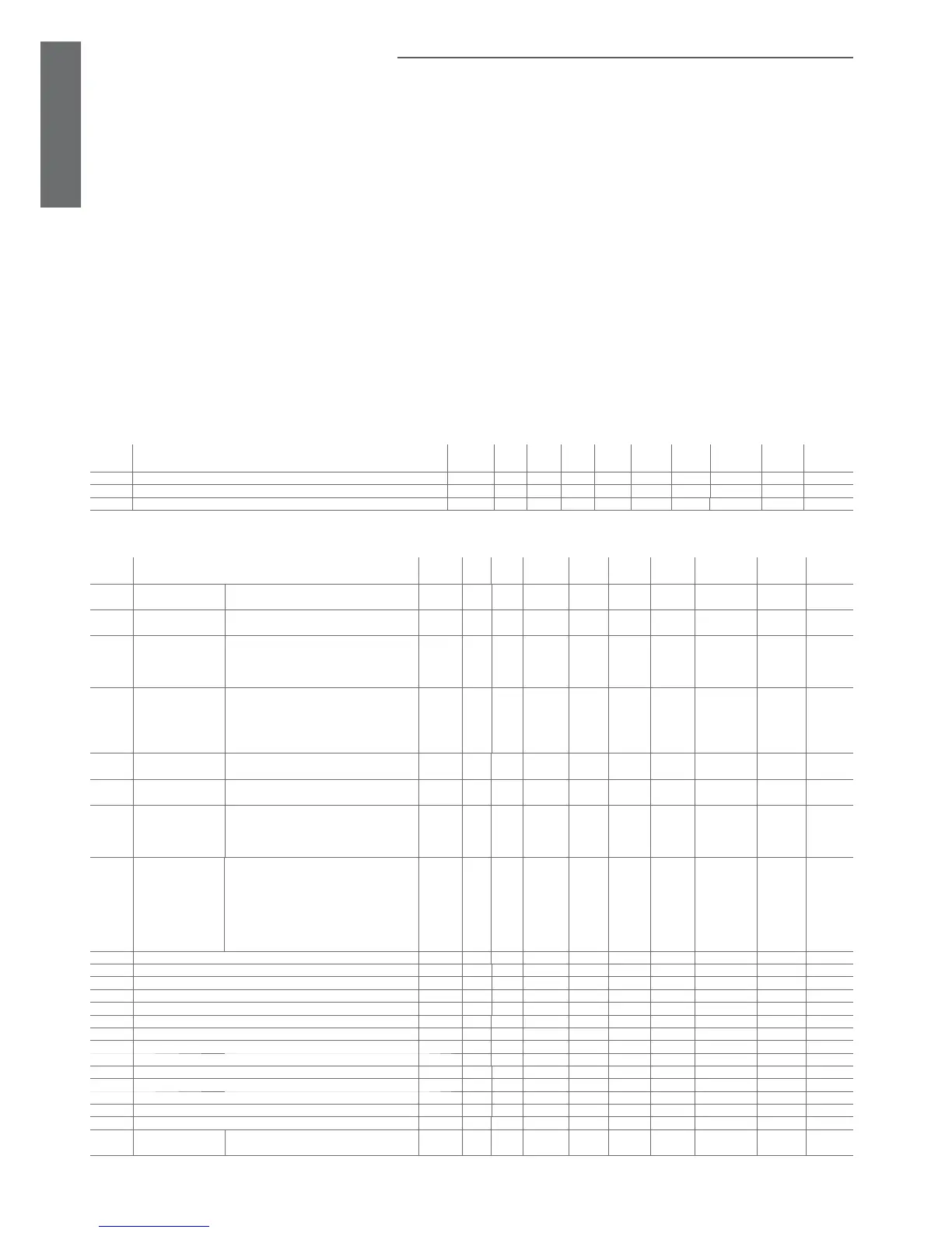
4.3.1 Evaporator and condenser temperature and pressure values: (d*)
display
indicat.
parameter and description default
level
min. max. UOM variat. default visibility supervis.
variable
Modbus variable
type
dtE Current value of DTE D 0 0 - - 0 - 99 (R) 99 Analog
dC1 Current value of DTC1 D 0 0 - - 0 - 100 (R) 100 Analog
dC2 Current value of DTC2 D 0 0 - - 0 - 101 (R) 101 Analog
Tab. 4.a
4.3.2 Probe setting parameters: (/*)
display
indicat.
parameter and description default
level
min. max. UOM variat. default visibility supervis.
variable
Modbus variable
type
/01 Probe type B1 0= not present
1= present
F 0 1 Flag 1 1 - 1 (R/W) 1 Digital
/02 Probe type B2 0= not present
1= present
F 0 1 Flag 1 0 - 2 (R/W) 2 Digital
/03 Probe type B3 0= not present
1= NTC Cond. Probe
2= NTC Out. Probe
3= differential control probe
F 0 3 int 1 0 - 14 (R/W) 221 Integer
/04 Probe type B4 0= not present
1= ON/OFF (D.I)
2= NTC Out. Probe
3= ratiometric cond. Probe, 5 Vdc
4= differential control probe
F 0 4 int 1 0 - 15 (R/W) 222 Integer
/05 Probe type B5 0= not present
1= present
F 0 1 Flag 1 0 X 3 (R/W) 3 Digital
/06 Probe type B6 0= not present
1= present
F 0 1 Flag 1 0 X 4 (R/W) 4 Digital
/07 Probe type B7 0= not present
1= NTC Cond. Probe
2= NTC Out. Probe
3= differential control probe
F 0 2 int 1 0 X 16 (R/W) 223 Integer
/08 Probe type B8
(expansion)
0= not present
1= ON/OFF
2= NTC Out. Probe
3= ratiometric cond. Probe, 5 Vdc
4= differential control probe
NB. if more than one differential control probe
is confi gured, the priority is: B8, B7, B4, B3
F 0 3 int 1 0 X 17 (R/W) 145 Integer
/09 Min. value voltage input F 0 /10 0.01 Vdc 1 50 P 18 (R/W) 225 Integer
/10 Max. value voltage input F /09 500 0.01 Vdc 1 450 P 19 (R/W) 226 Integer
/11 Pressure min. value F 0 /12 bar 1 0 P 1 (R/W) 1 Analog
/12 Pressure max. value F /11 99.9 bar 1 34.5 P 2 (R/W) 2 Analog
/13 Probe B1 calibration F -12.0 12.0 °C/°F 0.1 0.0 - 3 (R/W) 3 Analog
/14 Probe B2 calibration F -12.0 12.0 °C/°F 0.1 0.0 - 4 (R/W) 4 Analog
/15 Probe B3 calibration F -12.0 12.0 °C/°F 0.1 0.0 - 5 (R/W) 5 Analog
/16 Probe B4 calibration F -12.0 12.0 °C/bar/°F 0.1 0.0 - 6 (R/W) 6 Analog
/17 Probe B5 calibration F -12.0 12.0 °C/°F 0.1 0.0 X 7 (R/W) 7 Analog
/18 Probe B6 calibration F -12.0 12.0 °C/°F 0.1 0.0 X 8 (R/W) 8 Analog
/19 Probe B7 calibration F -12.0 12.0 °C/°F 0.1 0.0 X 9 (R/W) 9 Analog
/20 Probe B8 calibration F -12.0 12.0 °C/bar/°F 0.1 0.0 X 10 (R/W) 10 Analog
/21 Digital fi lter U 1 15 - 1 4 - 20 (R/W) 227 Integer
/22 Input limitation U 1 15 - 1 8 - 21 (R/W) 228 Integer
/23 Unit of measure 0= °C
1= °F
U 0 1 Flag 1 0 - 5 (R/W) 5 Digital
Table. 4.b
 Loading...


