64
LOAD LINE
220 Vac
GND
-+
Y
1
2
3
24 Vac
No Com Nc
YGND
1234
5678
24 Vac
G0 G00-10V 4-20mA
YGND
1234
5678
LOAD
N
L
-
+
LINE
N
L
Va c?
ENGLISH
µC
2
SE - +030220426 - rel. 2.0 - 03.08.2009
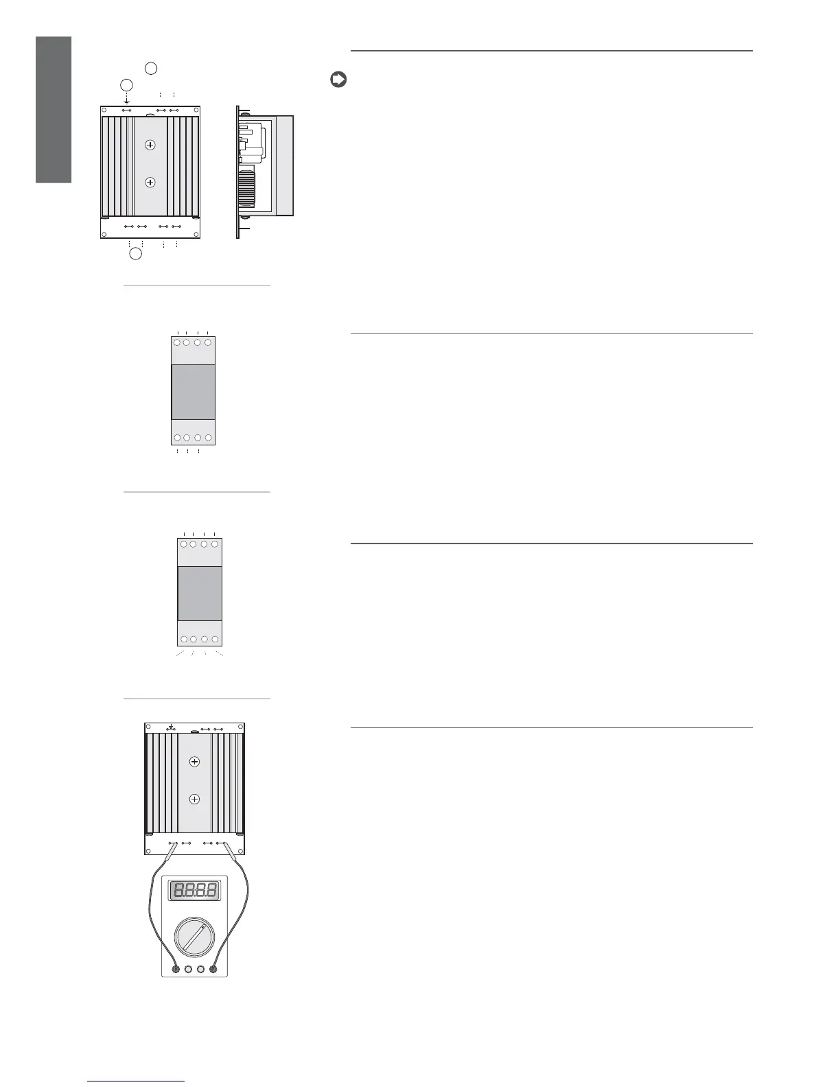
7.4 Fan speed control board (code MCHRTF*)
The phase cutting boards (code MCHRTF****) are used to control the speed of the condenser fans.
IMPORTANT: The power supply to the µC
2
SE (G and G0) and the MCHRTF**** board must be in
phase. If, for example, the power supply to the µC
2
SE system is three-phase, make sure that the
primary of the transformer supplying the µC
2
SE board is connected to the same phase that
is connected to terminals N and L on the speed control board; therefore, do not use
380 Vac/24 Vac transformers to supply the controller if the phase and neutral are used to directly
power the speed control boards.
Connect the earth terminal (where envisaged) to the earth in the electrical panel.
Key:
1. to µchiller;
2. earth;
3. to motor.
3. al motore.
7.5 Fan ON/OFF control board (code CONVONOFF0)
The relay boards (code CONVONOFF0) are used for the ON/OFF management of the condenser fans.
The control relay has a switchable power rating of 10 A at 250 Vac in AC1 (1/3 HP inductive).
7.6 PWM to 0 to 10Vdc (or 4 to 20 mA)conversion board for fans
(code CONV0/10A0)
The CONV0/10A0 boards convert the PWM signal at terminal Y on the µC
2
SE to a standard 0 to 10 Vdc (or
4 to 20 mA) signal. The FCS series three-phase controllers can be connected to the µC
2
SE without using
this module.
7.7 Minimum and maximum fan speed calculation
This procedure should only be performed when the fan speed control boards are sued (code MCHRTF*).
it must be stressed that if the ON/OFF modules (code CONVONOFF0) or alternatively the PWM to 0 to
10 V converters (code CONV0/10A0) are used, parameter F03 should be set to zero, and parameter F04
to the maximum value.
Given the different types of motors existing on the market, the user must be able to set the voltages
supplied by the electronic board corresponding to the minimum and maximum speeds. In this regard
(and if the default values are not suitable), proceed as follows:
set parameter F02= 3 and set F03 and F04 to zero;•
the condenser control set point (evaporator in HP mode) has been modifi ed to take the output signal •
to the maximum value (PWM);
increase F04 until the fan operates at a suffi cient speed (make sure that, after having stopped it, it can •
rotate freely when released);
“copy” this value to parameter F03; this sets the voltage for the minimum speed;•
connect a voltmeter (set for AC, 250V) between the two “L” terminals (the two external contacts);•
increase F04 until the voltage stabilises at around 2 Vac (inductive motors) or 1.6, 1.7 Vac (capacitive •
motors). Once the value has been found, it will be evident that even when increasing F04 the voltage
no longer decreases. In any case do not increase F04 further so as to avoid damaging the motor;
restore the correct condenser set point (evaporator in HP mode).•
The operation is now completed.
Fig. 7.d
Fig. 7.e
to µchiller
Fig. 7.f
to µchiller
Fig. 7.g
 Loading...


