70
ENGLISH
µC
2
SE - +030220426 - rel. 2.0 - 03.08.2009
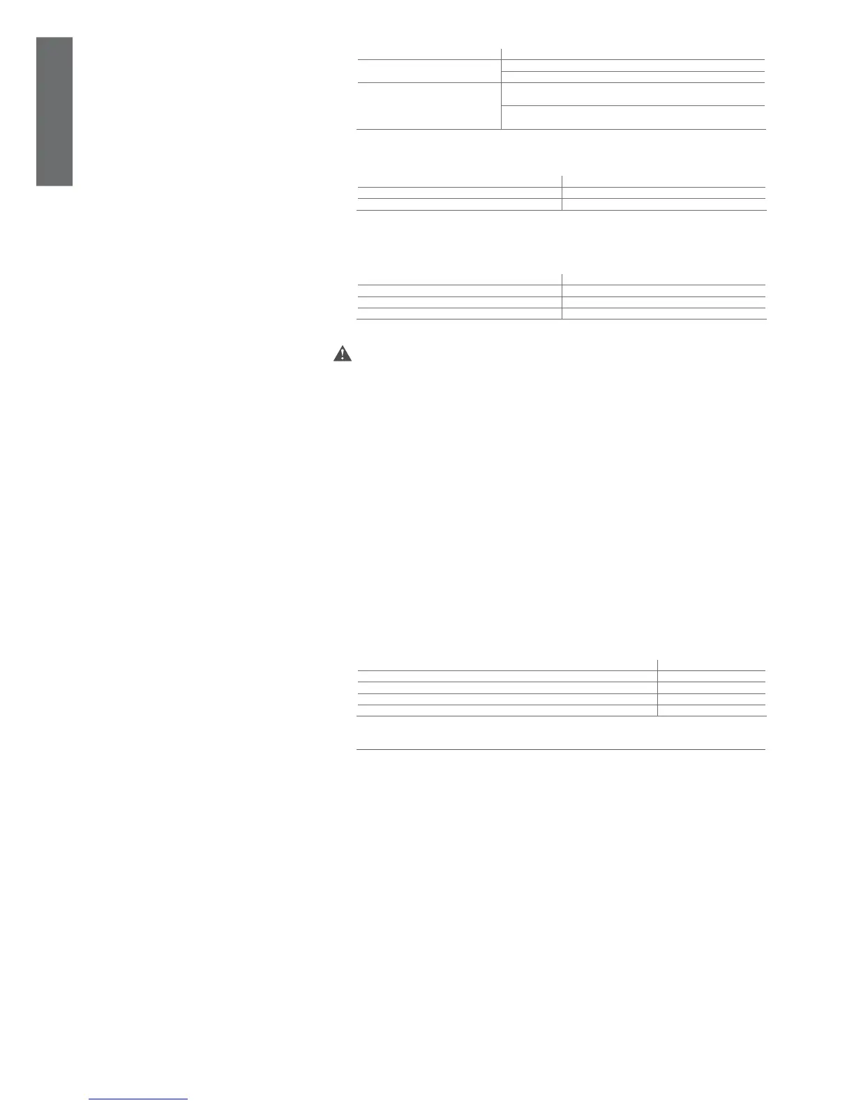
Functional characteristics
Resolution of the analogue inputs Temperature probes: range -40T80 °C, 0.1 °C
Temperature measurement error Range -20T20 °C, ±0.5 °C ( excluding probe)
Range -40T80 °C, ±1.5 °C ( excluding probe)
Pressure measurement error The % error with a voltage reading with a range of input from 0.5 to 4.5
is ± 2% (excluding probe).
The error in the converted value may vary according to the settings of
parameters /9, /10, /11, /12
Table 10.b
Characteristics of the connectors
The connectors may be purchased using CAREL code (MCHCON0***) or from the manufacturer Molex
®
Molex
®
codes of the connector Number of pins
39-01-2120 12
39-01-2140 14
Table 10.c
Max. number of insertion/removal cycles for the connectors: 25 cycles
Code of the contacts according to the cross-section of the connection cables to the 12- and 14-pin
connectors (use the special Molex
®
tool code 69008-0724 for crimping
Molex
®
code of the contact Cross-section of cables allowed
39-00-0077 AWG16 (1,308 mm
2
)
39-00-0038 AWG18-24 (0,823...0,205 mm
2
)
39-00-0046 AWG22-28 (0,324...0,081 mm
2
)
Table 10.d
In addition, the pre-wired kits MCHSMLC*** are also available
WARNINGS
If one transformer is used to supply both the µC•
2
SE and the accessories, all the G0 terminals on the
various controllers or the various boards must be connected to the same terminal on the secondary,
and all the G terminals to the other terminal on the secondary, so as to avoid damaging the
instrument;
For use in residential environments, use shielded cable (two wires + shield earthed at both ends, AWG •
20-22) for the tLAN connections (EN 55014-1).
Avoid short-circuits between V+ and GND so as to not damage the instrument; •
Perform all the maintenance and installation operations when the unit is not connected to the power •
supply;
Separate the power cables (relay outputs) from the cables corresponding to the probes, digital inputs •
and serial line;
Use a transformer dedicated exclusively to the electronic controllers for the power supply.•
Protection against electric shock and maintenance warnings
The system made up of the control board (MCH200003*) and the other optional boards (MCH200002*,
MCH200485*, MCHRTF****, CONVONOFF*, CONV0/10A*, EVD000040*) represents a control device to
be integrated into class 1 or class 2 appliances.
The class of protection against electric shock depends on how the control device is integrated into the
unit built by the manufacturer.
Disconnect power before working on the board during assembly, maintenance and replacement.
The protection against short circuits must be guaranteed by the manufacturer of the appliance that the
controller will be fi tted on.
Maximum length of the NTC/ratiometric probe
NTC/ratiometric probe connection cables 10 m
digital input connection cables 10 m
power output connection cables 5 m
fan control output connection cables 5 m
power cables 3 m
Table 10.e
10.2 Software updates
10.2.1 Notes for version 1.1
First release.
10.2.2 Notes for version 1.2
Optimised use of the programming key.
10.2.3 Notes for version 1.3
Implemented direct current operation.
Use EXP. version 1.5 or higher.
10.2.4 Notes for version 1.4
Implemented a differential relating to the working set point for electric heaters in air- and water-source
units. Implemented cooling only air-source unit with electrical heaters operating in heating mode only.
Implemented new logic for the activation of the alarm relays.
Implemented new logic for the management of the high pressure alarm.
Implemented management of minimum damper opening.
Implemented damper inactivity time in freecooling or freeheating mode.
Optimised management of damper closing for minimum outlet temperature limit.
Implemented alarm reset from µAD.
10.2.5 Notes for version 1.6
Improved Modbus
®
communication with supervisory system
10.2.6 Notes for version 1.7
Implemented second antifreeze set point (A14)
 Loading...


