65
ENGLISH
µC
2
SE - +030220426 - rel. 2.0 - 03.08.2009
7.8 Programming key (code PSOPZKEYA0)
The programming keys PSOPZKEY00 and PSOPZKEYA0 for CAREL controllers are used for copying the
complete set parameters for µC
2
SE.
The keys must be connected to the connector (4 pin AMP) fi tted on the controllers, and can work with
the instruments ON or OFF, as indicated in the operating instructions for the specifi c controller.
The two main functions (upload/download) that can be selected through two dip-switches (which are
placed under the battery cover). They are:
Loading to the key the parameters of a controller (UPLOAD);•
Copying from the key to one or more controllers (DOWNLOAD).•
Warning: the copying of the parameters is allowed only between instruments with the same code.
Data loading operation to the key is always allowed. To make identifi cation of the key easier CAREL has
inserted a label on which you can describe the loaded programming or the machine to which you are
referring.
IMPORTANT NOTE: the key can be used only with controllers µC
2
SE that have the same Firmware
version.
UPLOAD - copying the parameters from an instrument to the key:
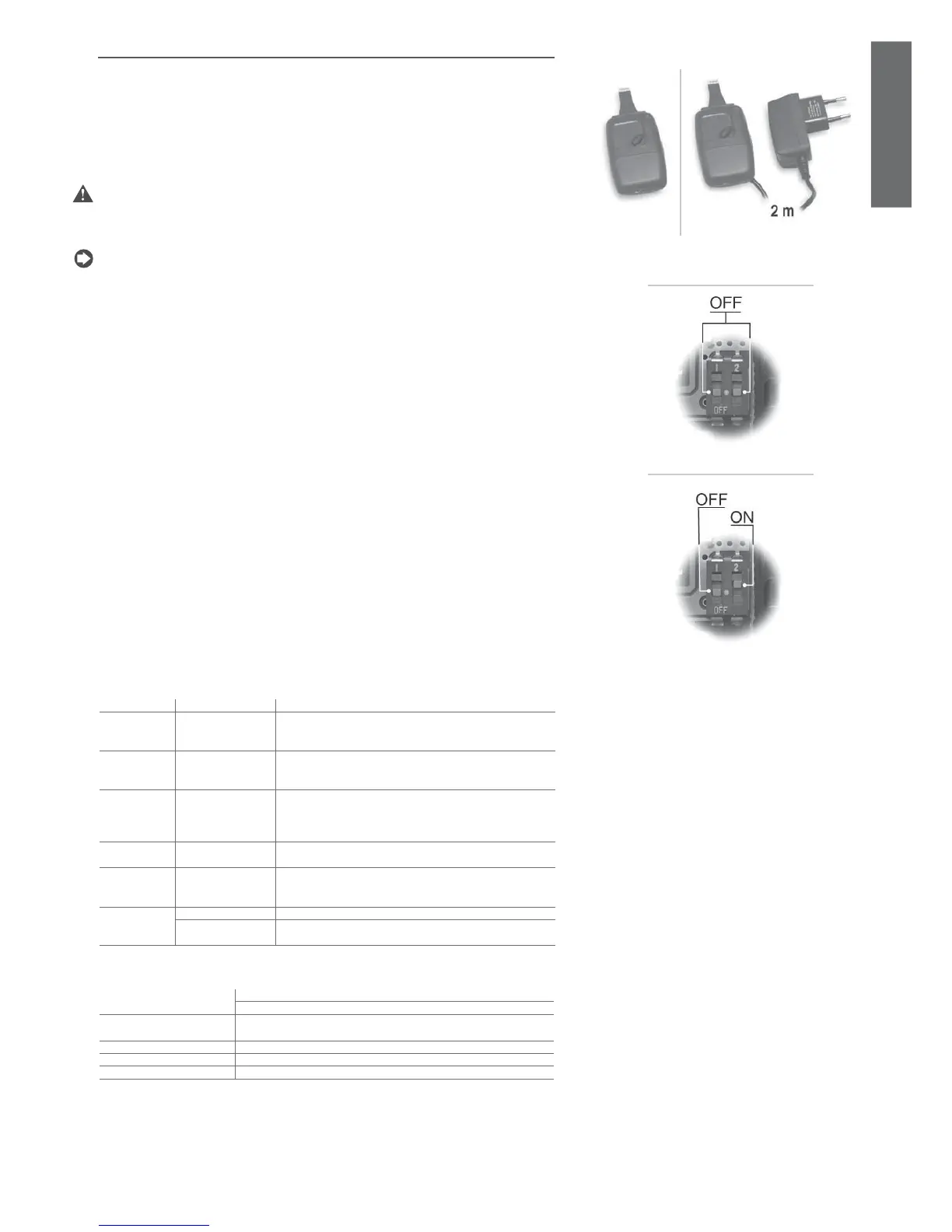
open the rear hatch of the key and place the two dip-switches in the OFF position (see Fig. 7.j.a). Close •
the hatch;
connect the key to the connector of the instrument;•
press the button on the key and keep it pressed, checking the LED signal sequence: at fi rst it is red, •
after a few seconds it becomes green;
if the sequence of signals is as indicated above, the copying operation has been completed correctly •
(green LED ON), the button can be released and the key disconnected from the instrument; in case of
different signals: if the green LED doesn’t turn on or if there are some fl ashes, there’s a problem. Refer
to the corresponding table for the meaning of the signals.
DOWNLOAD - copying the parameters from the key to the instrument:
open the rear hatch of the key and place the dip-switch n. 1 in the OFF position and the dip-switch n. 2 •
in the ON position (see Fig. 7.j.b). Close the hatch;
connect the key to the connector of the instrument;•
press the button on the key and keep it pressed, checking the LED signal sequence: at fi rst it is red, •
after a few seconds it becomes green;
if the sequence of signals is as indicated above, the copying operation has been completed correctly •
(green LED ON), the button can be released; after a few seconds the LED turns off and the key can be
disconnected from the instrument;
in case of different signals: if the green LED doesn’t turn on or if there are some fl ashes there’s a •
problem. Refer to the corresponding table for the meaning of the signals.
The operation takes maximum 10 seconds to complete. If after this period the completed operation signal
hasn’t yet appeared, i.e. the green LED ON, try releasing and pressing the button again. In the event of
fl ashes, refer to the corresponding table for the meaning of the signals.
LED signal error meaning and solution
red LED fl ashing Flat batteries at the
beginning of the
copying
The batteries are fl at, the copying cannot be carried out.
Replace the battery (only on PSOPZKEY00).
green LED
fl ashing
Flat batteries at the end
of the copying (only on
PSOPZKEY00)
The copying operation has been carried out correctly but at the end
of the operation the voltage of the batteries is low.
It is advisable to replace the batteries.
Alternate red/
green LED
fl ashing
(orange signal)
Not compatible
instrument
The setup of the parameters cannot be copied since the model of
the connected parameters is not compatible. Such error happens
only with the DOWNLOAD function, check the controller code and
make the copy only on compatible codes.
red and green
LEDs ON
Copying error Error in the copied data. Repeat the operation; if the problem
persists, check the batteries and the connections of the key.
red LED always
ON
Data transmission error The copying operation hasn’t been completed because of serious
data transmission or copying errors. Repeat the operation, if the
problem persists, check the batteries and the connections of the key.
LEDs OFF Batteries disconnected Check the batteries (for the PSOPZKEY00)
Power supply not
connected
Check the power supply (for the PSOPZKEYA0)
Table 7.d
Technical specifi cations
Power supply to the
PSOPZKEY00
- Use three 1.5 V 190 mA batteries (Duracell D357H or equivalent)
- Maximum current supplied 50 mA max.
Power supply to the
PSOPZKEYA0
- switching power supply:
Input 100 to 240 V~; (-10%, +10%); 50/60 Hz; 90 mA. Output: 5 Vdc; 650 mA
Operating conditions 0T50°C r.H. <90% non-condensing
Storage conditions -20T70°C r.H. <90% non-condensing
Case Plastic, dimensions 42x105x18 mm including prod and connector Figs. 1 and 2
Table 7.e
( Here we have dealt only with the base functions of the instrument. For the remaining specifi c functions, see the
manual of the instrument that is being used).
Fig. 7.h Fig. 7.i
Fig. 7.j.a
Fig. 7.j.b
 Loading...


