Standard air-conditioning units
Carel Cod. +030221421 – Rel. 1.2 – April, 11, 2003
6
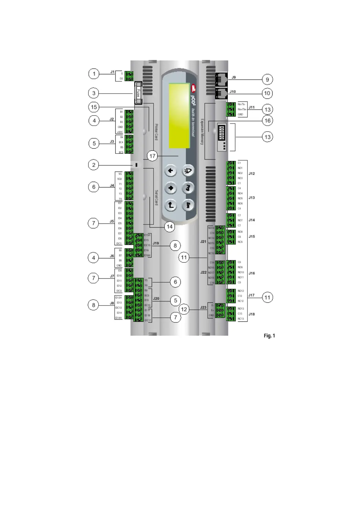
1.4 pCO2 MAIN BOARD
The pCO2 board is described below, with reference to the general layout.
Key:
1. –G (+), G0 (-)- power supply connector
2. supply voltage yellow LED and overload alarm red LED
3. 250Vac fuse, 2
nd
delayed (T2 A)
4. NTC, 0/1V, 0/10V, 0/20mA, 4/20mA universal analogue inputs
5. NTC, PT1000, On-Off passive analogue inputs
6. 0/10V analogue outputs
7. 24Vac/Vdc digital inputs
8. 230Vac or 24Vac/Vdc digital inputs
9. synoptic terminal connector (external panel with direct signalling)
10. connector for all pCO* series standard terminals and for application program download
11. relay digital outputs
12. expansion card connector
13. pLAN local network connector, addressing and LED
14. port for serial card insertion (Rs485 for supervision, Rs232 for modem or Echelon interfacing)
15. port for parallel printer connection card insertion
16. port for memory expansion or programming key card insertion
17. built-in terminal (LCD, buttons and LEDS)
 Loading...


