Standard air-conditioning units
Carel Cod. +030221421 – Rel. 1.2 – April, 11, 2003
12
3.3.1 SETTING THE pCO1 ADDRESS
Operations to be carried out for pCO1 boards pLAN addressing:
1. Cut pCO1 board power off and connect an external terminal with pLAN address“0”
2. Power pCO1 board keeping terminal buttons Alarm + Up pressed until a screen is displayed
3. After the screen is displayed, carry out the indicated operations, that is key in the numerical pLAN address (1,2,3….) by using buttons
Up and Down, then confirm by pushing Enter
4. Cut pCO1 board power off
5. If required, assign the correct pLAN address to the external terminal, if provided
6. Power pCO1 board.
3.3.2 SETTING THE ADDRESS OF PCO2, EXTERNAL TERMINALS AND VALVE DRIVERS
This paragraph indicates the addresses to be set on pCO2 boards, external terminals and valves drivers. If pCO1 boards are being used, refer to
the previous paragraph as for boards only (as for terminals and drivers, the following indications are valid).
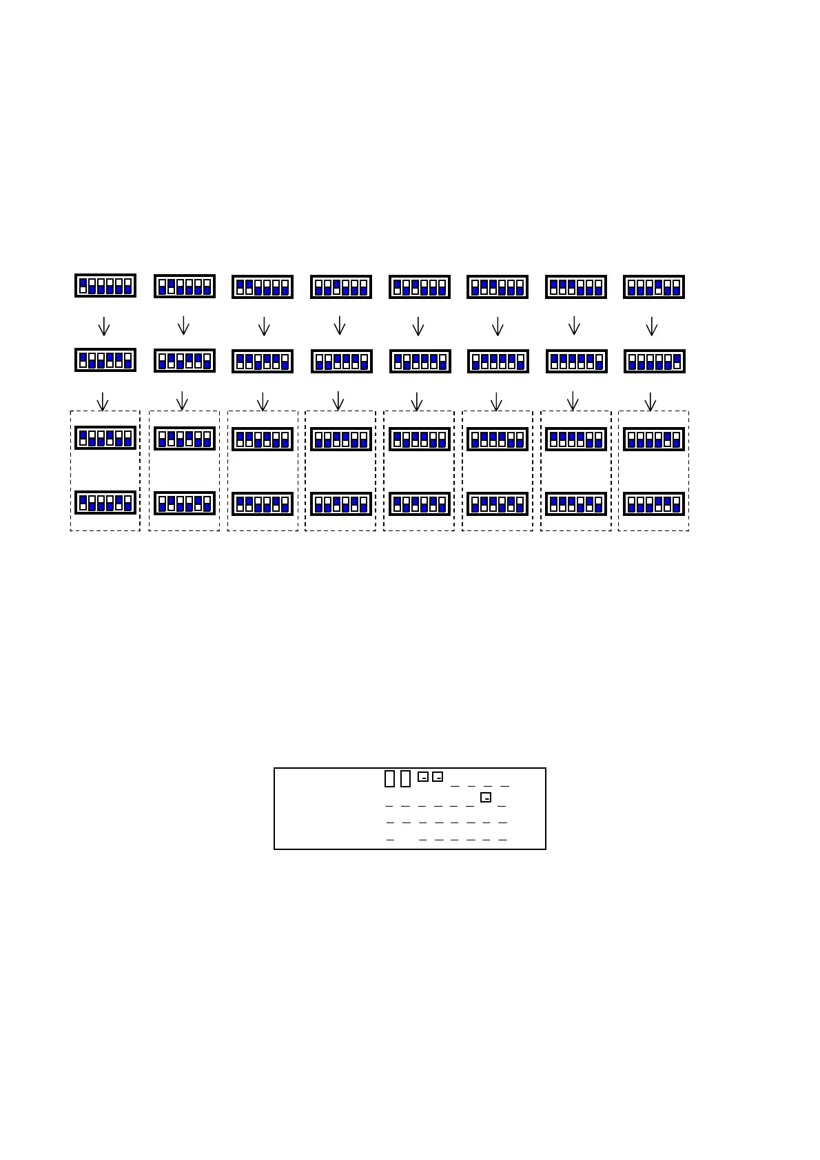
Each external terminal refers to one board and two electronic valves, that is:
• board add. 1 ! valves add. 9/17 ! terminal add. 25,
• board add. 2 ! valves add. 10/18 ! terminal add. 26…..
The terminals Menu main screen displays the address of the connected board in the upper right corner. Terminal add. 32 allows controlling all
boards without requiring other terminals or in addition to the other terminals; as a matter of fact, the program allows terminal with add. 32 to
access the parameters of all connected boards, one by one. Passage among the boards can be executed by simply pushing button info.
In all other program screens, the address of the connected board can be known by pushing button info.
3.4 pLAN STATUS
When starting the system, the pLAN network could undergo some problems (failed boards and terminals displays start-up) due to improper
electrical connections or to the fact that incorrect addresses have been assigned. By means of a special screen, the pLAN network state can be
displayed in real time, thus identifying which devices (boards and terminals) are properly connected and addressed. To display the special
screen, push buttons Up-Down-Enter of any network terminal simultaneously for at least 10 sec. After the first 5 seconds, a screen is displayed;
continue for another 5 seconds until the following screen is displayed:
NetSTAT
T: xx
Enter
To Exit
8
16
24
32
1
9
17
25
As it can be seen, network addresses from 1 to 32 are displayed, together with a symbol indicating if a terminal (small rectangle) or a board /
valve driver (big rectangle) is concerned. The dash indicates that the board / terminal has incorrect address or is connected improperly. In case
the symbols appear and disappear, it means that pLAN is unstable or, more probably, that repeated addresses are present. The number following
T indicates the address of the terminal being used. The example indicates that the network consists of two boards or valves drivers with address
1, 2, and of three terminals with address 3, 4, 15. After the screen is checked, cut network power off, verify connections and addresses and
power the system again.
3.5 CHECK pLAN ADDRESS
During pCO1 – pCO2 board normal operation, the board pLAN address can be checked at any time by pushing the red button (Prg+Enter in
case a built-in terminal is being used). The information appears on the display first row, covering a part of the displayed screen for 2 seconds.
The pLAN address is always displayed in the M0 Menu screen.
Add. 1 Add. 2 Add. 3 Add. 4 Add. 5 Add. 6
Card 1 Card 2 Card 3 Card 4 Card 5 Card 6 Card 7 Card 8
A
25 A
26 A
2
A
28 A
2
A
30 A
31 A
32
Terminal 1 Terminal 2 Terminal 3 Terminal 4 Terminal 5 Terminal 6 Terminal 7 Terminal 8
Add. 9 Add. 10 Add. 11 Add.12 Add. 13 Add. 14 Add. 15 Add. 16
Valve 1 Valve 3 Valve 5 Valve 7 Valve 9 Valve 11 Valve 13 Valve 15
Add 17 Add 18 Add 19 Add 20 Add 21 Add 22 Add 23 Add 24
Valve 2 Valve 4 Valve 6 Valve 8 Valve 10 Valve 12 Valve 14 Valve 16
 Loading...


