Standard air-conditioning units
Carel Cod. +030221421 – Rel. 1.2 – April, 11, 2003
11
3.0 BOARD CONNECTION MANAGEMENT (pLAN)
The pLAN network identifies a physical connection between the boards (pCO1 or pCO2) and the external terminals.
pLAN=p.CO L.ocal A.rea N.etwork. Boards connection in pLAN network allows exchanging variables from a board to another, according to a
logic established by the program, to make them work together in a functional way.
The variables exchanged among the boards are already established by the program, as well as the direction they must follow and from which
they come. Therefore, they cannot be programmed by the user, who must execute the electrical connections only.
Do not execute pCO1 – pCO2 mixed connections, use exclusively boards of the same type.
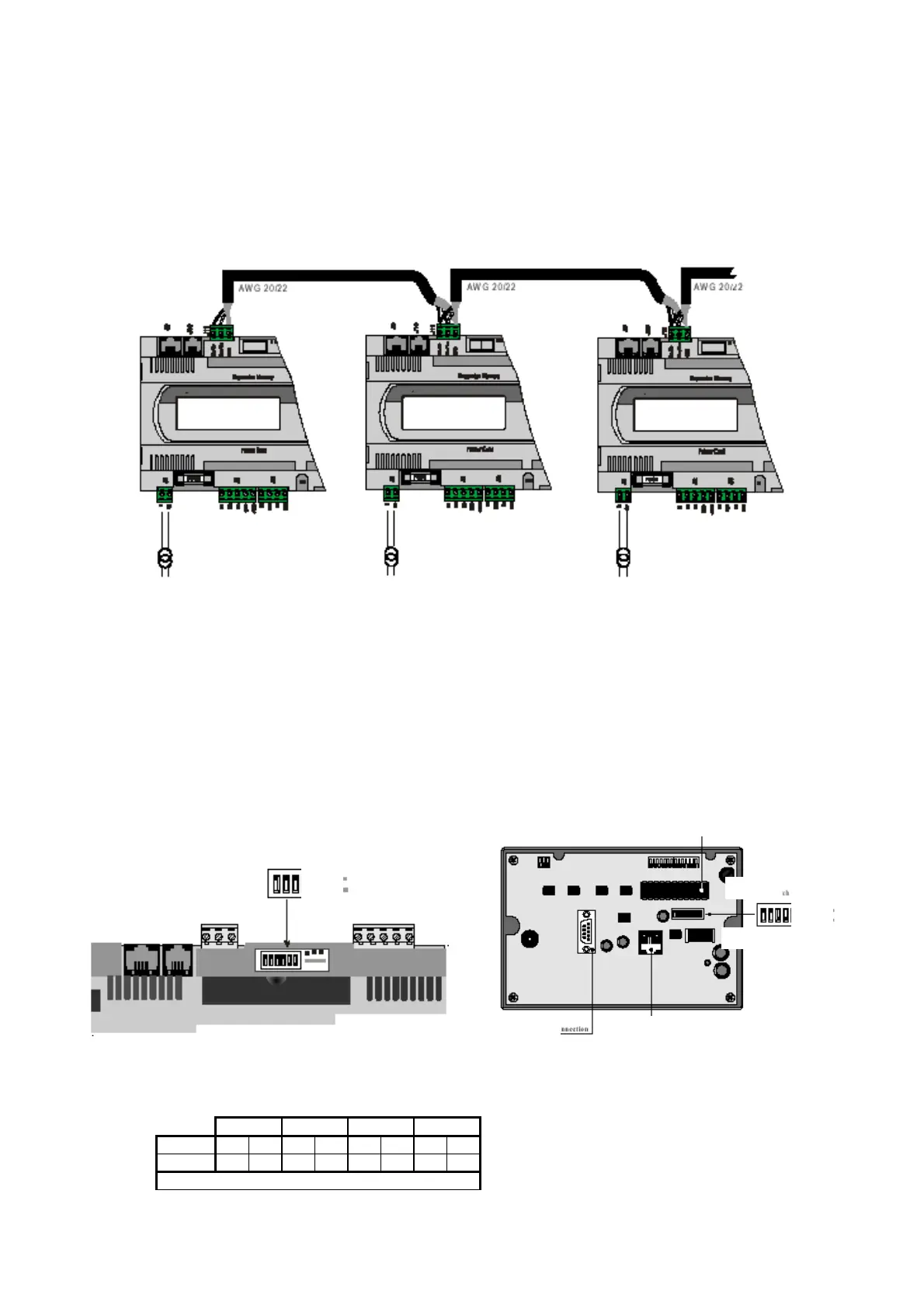
3.1 pLAN PHYSICAL CONNECTIONS
The pLAN electrical connection among pCO1 or pCO2 boards is executed in parallel with 3 wires, from board to board, by using connector J11;
the data are sent through Rs485 logic; no additional device is required. As usual, terminals shall be connected to the boards by the relevant
telephone cable (code S90CONN*).
3.2 SETTING THE pLAN ADDRESS
For pLAN proper operation, the boards and the external terminals (not the built-in terminals) shall be addressed.
Even if only one board is being used, address 1 shall be set on the board and address 25 shall be set on the external terminal, if any. If the same
address is assigned to two network elements, the pLAN cannot work!
The available addresses range from 1 to 32 (in binary logic), where 32 is the total number of boards + terminals + electronic expansion valves
that can be connected with the pLAN, divided into 8 boards (addresses 1–8), 16 electronic valves (addresses 9–24) and 8 external terminals
(addresses 25–32).
In case external terminals or electronic valves are not used, the boards maximum number (8) keeps unchanged. The addresses to be assigned to
boards, valves and terminals are already established to facilitate installation and are listed in the following paragraph.
3.3 HOW TO ASSIGN THE ADDRESSES
The pLAN addresses are set with binary logic by changing the dip switch position on the back of the external terminals, on pCO2 boards (see
figure below) and inside the electronic valves drivers, with all devices compulsorily not powered; in the pCO1, address is numerical and is
assigned in a different way by an external terminal.
To read the address of a pCO2 board, external terminal or driver without remembering the binary code by heart, follow this simple rule: if the
switch is in position 1, add up value 1 for switch 1, 2 for switch 2, 4 for switch 3, 8 for switch 4, and so on. Do not add up any values for the
switches in position 0. In the example below, the selected address is: 1 + 2 + 4 + 8 = 15.
Switch1 Switch2 Switch3 Switch4
State off on off on off on off on
P 0 1 0 2 0 4 0 8
Address = P(Sw1)+P(Sw2)+P(Sw3)+P(Sw4)
On
Of
microprocessor
On
Of
printer
pCO2-pCO1 connector
 Loading...


