Standard air-conditioning units
Carel Cod. +030221421 – Rel. 1.2 – April, 11, 2003
5
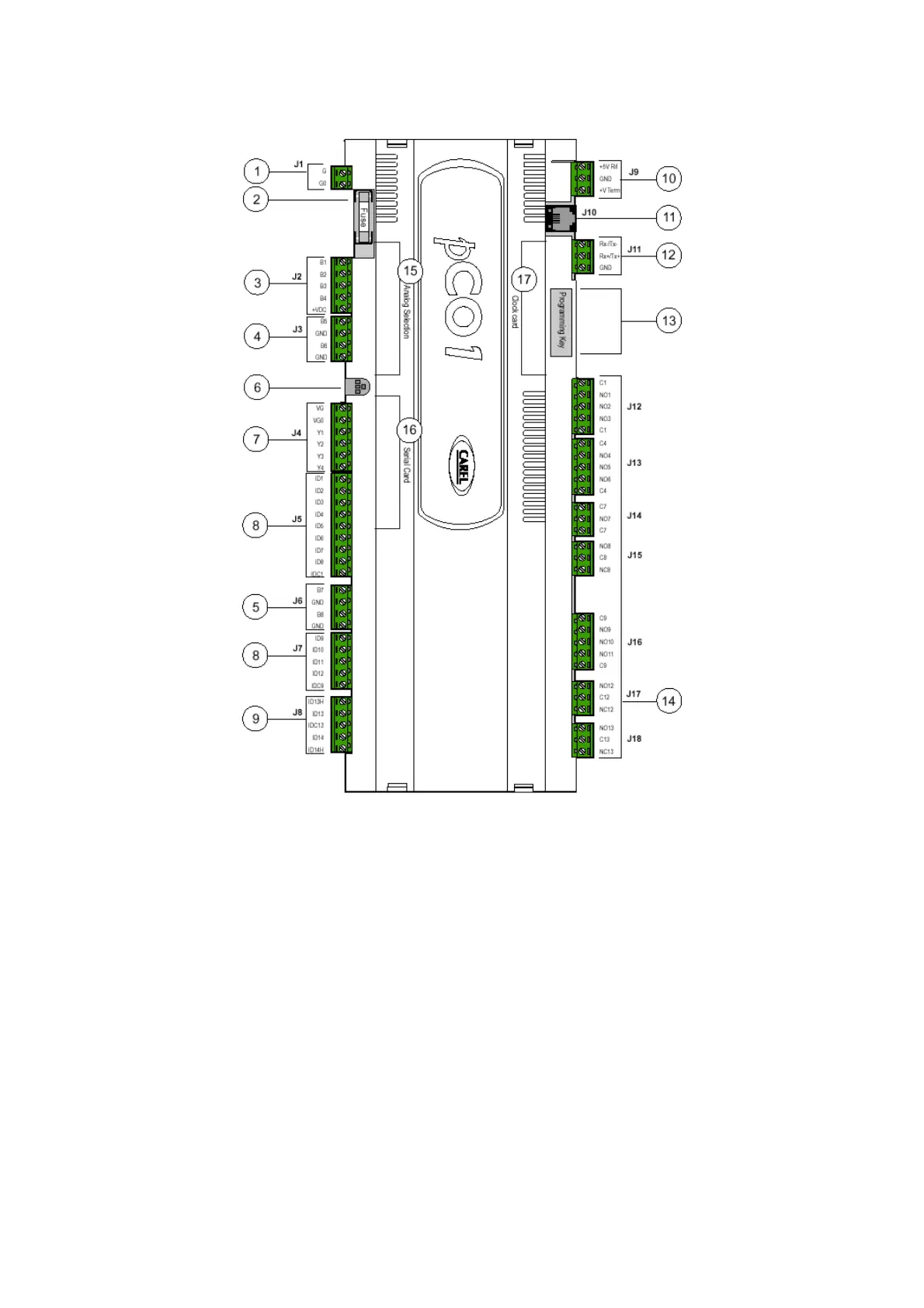
1.3 pCO1 MAIN BOARD
The pCO1 board is described below, with reference to the general layout.
Key:
1. –G (+), G0 (-)- power supply connector
2. 250Vac fuse, 2
nd
delayed (T2 A)
3. NTC, 0/1V, 0/5V, 0/20mA, 4/20mA universal analogue inputs
4. NTC and On-Off passive analogue inputs
5. NTC passive analogue inputs
6. supply voltage yellow LED + 3 signalling LEDS
7. 0/10V analogue outputs and cutting phase PWM outputs
8. 24Vac/Vdc digital inputs
9. 230Vac or 24Vac/Vdc digital inputs
10. connector with Vrif for 5V ratiometric probes feeding and V Term for terminal feeding
11. connector for all pCO* series standard terminals and for application program download
12. pLAN local network connector
13. programming key connector
14. relay digital outputs
15. port for analogue inputs type selection
16. port for serial card insertion (Rs485 for supervisor, Rs232 for modem, Gateway protocol inverter)
17. port for clock card insertion
 Loading...


