Standard air-conditioning units
Carel Cod. +030221421 – Rel. 1.2 – April, 11, 2003
41
22.1 SHARED EXTERNAL TERMINAL
The Menu main screen shows the pLAN address of the displayed board in the upper right corner;
in private displays, it is a fixed number corresponding to the pLAN address of the board they are
connected with (1-8).
Terminal no. 32 allows selecting the board to be displayed by pushing button Info; whenever a
button is pressed, the address displayed in the upper right corner increases by 1 and the display
shows the parameters of the board selected among the connected ones.
In case of a board alarm, the shared terminal automatically connects with it to display the alarm.
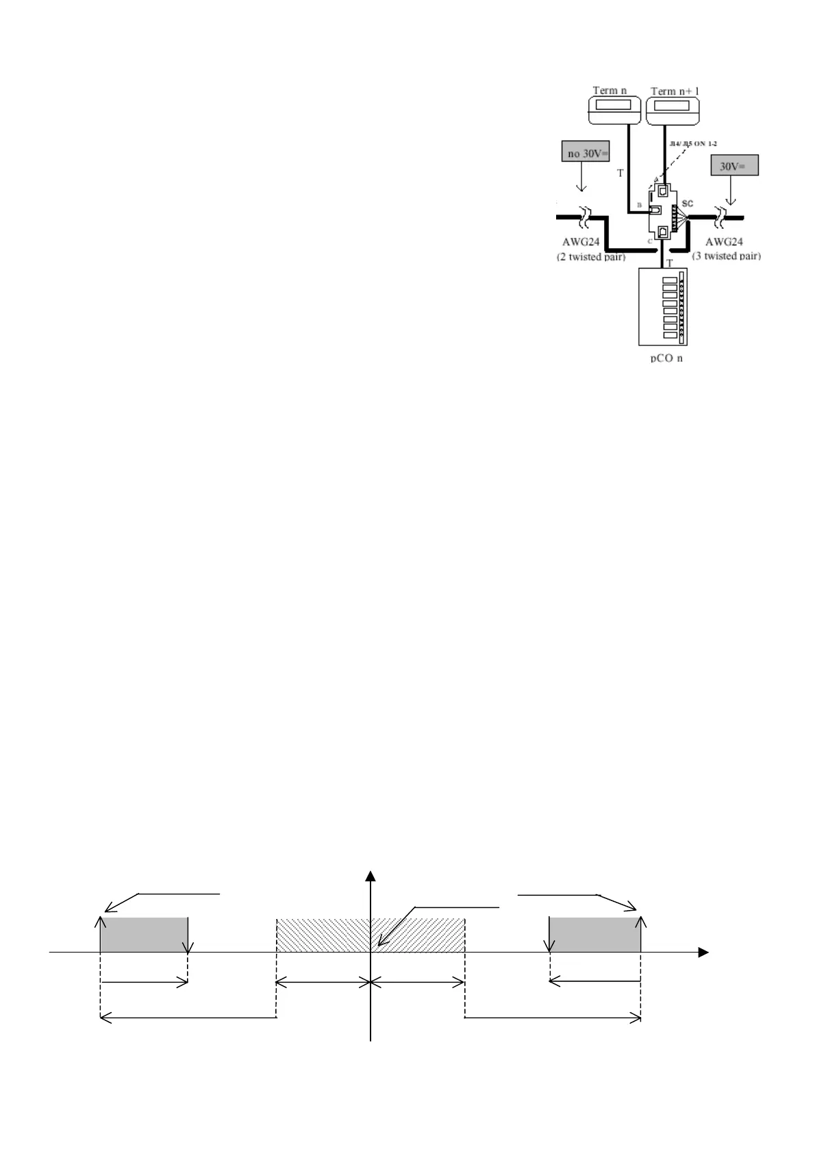
The shared terminal can be connected to any network board; in case of boards equipped with
built-in terminal, the shared terminal must be connected to connector J10 by a telephone cable; in
case of boards equipped with private external display, the shunt code TCONNJ6000, shown in
the following figure, is required (private=Term n; shared=Term n+1):
The shared terminal only allows printing all boards alarms and parameters.
22.2 AUTOMATIC START AND STAND-BY UNITS
The boards connected with pLAN network may be managed directly by the program under
“critical situations”, that is in case of failure (alarms, black-out…) or due to “Rotation” and
“Forcing” functions.
The program acts based on some parameters that can be displayed and modified on the board
with pLAN address 1:
• Boards mode operation: Not present, Present/No Rotation, Present/Rotation. These are 8 parameters, one for each board. Not present:
unit not connected. Present/No Rotation: unit physically connected with pLAN network but not involved in the rotation function
(however, unit can manage the shared terminal, printing and Carel’s Master Control function). Present/Rotation: unit involved in
Rotation too.
• Number of units in stand-by
mode: this parameter establishes the number of units, among the ones selected in Present/Rotation mode,
that must be set to stand-by
mode (turned off, waiting for enabling) when starting the unit by button. The parameter is automatically
included between 0 and the total number of Present/Rotation units minus one, to ensure start-up of at least one unit.
IMPORTANT. The following functions cannot be executed if:
• at least two units selected in Present/controlled mode are not present
• the stand-by
units set number is 0
The board with pLAN address 1 provides for functions management; if the board is disconnected from pLAN network or it shuts down due to a
black-out, the stand-by
boards enable and the functions will be suspended until unit 1 is reset. On the contrary, unit 1 stop by On-off or remote
On-off button does not interrupt network functions execution.
22.2.1 CRITICAL SITUATIONS
Units in Present/Rotation and stand-by modes are enabled in any of the following critical situations concerning the running boards:
• one of the boards has power cut off (black-out)
• one of the boards signals a Serious alarm that enables alarm relay no. 8 (each alarm can be programmed as serious or non-serious)
• one of the boards disconnects from pLAN network due to Rs485 line disconnection
• one of the boards is shut down by button or remote On-off digital input
• one of the boards is shut down due to a serious alarm (refer to alarms table).
In case a running unit is involved in any of the listed situations, a stand-by
board is automatically enabled to reset the number of running units.
If, for example, two running units break or disconnect, the program enables two stand-by
units; when one of the units under critical situation
resets, it is started again and the spare unit returns to stand-by
mode. If a critical situation involves the stand-by units, no pLAN action occurs,
with the exception of alarm signalling on the involved unit.
22.2.2 FORCING
Units in Present/Rotation and stand-by modes are enabled automatically in case a running unit does not reach the temperature set point for a
certain time interval due to an excessive thermal load. Each unit running in such a situation can require enabling of a stand-by
unit. The
parameters to be set for forcing are Differential, Offset and Delay time, different for heating and cooling. The following diagram shows the
forcing function:
12.0 16.0 20.0 23.0 26.0 34.0
Ambient
tem
.
°C
Temperature set
Warm band Cold band
Warm forcin
differential Cold forcin
differential
3°C 3°C
°
Warm forc. offset
8°C 8°C
°
Cold forc. offset
Forcing delay in
heating mode
Forcing delay in
cooling mode
 Loading...


