Standard air-conditioning units
Carel Cod. +030221421 – Rel. 1.2 – April, 11, 2003
37
21.0 SUPERVISION
pCO1 and pCO2 can be connected with a local or remote supervisory PC, a GSM or traditional modem and the most spread BMS (Modbus,
Bacnet, Lonworks). To be used, the listed functions require the installation of optional cards (Rs485, Rs232, LON) or Gateways (devices able to
interpret different communication protocols).
21.1 CAREL SUPERVISOR
The local connection between pCO1 – pCO2 board and a supervisory PC requires the insertion of the Rs485 additional card (pCO2:
PCO2004850; pCO1: PCO1004850) into the “Serial card” port. From the additional card, connect to the Rs485 serial line up to the
Rs485/Rs232 converter supplied by Carel (PC485KIT00) for connection with the PC.
In case of remote supervisor with supervisory PC connected with the telephone line, simply install the Rs232 optional card (pCO2:
PCO200MDM0; pCO1: PCO100MDM0) and connect it to a traditional modem (not GSM). The program allows managing the modem and
setting the phone numbers to be called. As for connections, refer to the instruction sheet.
21.2 BMS
The connection with the BMS supervisory systems is executed in different ways.
Lonworks: insert the additional card into the “Serial card” port (pCO2: PCO20LFTTL / PCO20L485L; pCO1: PCO10LFTTL / PCO10L485L)
and connect as prescribed in the instruction sheet. Enable LON function on the LCD terminal.
Modbus: insert the Rs485 additional card; the card only is required since the program manages this protocol by itself.
Bacnet: insert the Rs485 additional card and connect it with Carel’s gateway code GATEWAYBN0 by Rs485 line.
Owners’ BMS: Carel has developed many other Gateways for interfacing with less spread BMS, i.e. OTE.
21.3 GSM PROTOCOL
By selecting the GSM protocol, SMS (text) messages can be sent to and from GSM phones, using a GSM modem. The pCO1 or pCO2 sends a
message to the phone in the event of alarms, and can receive messages from the telephone at any time; the user can in fact use a GSM phone to
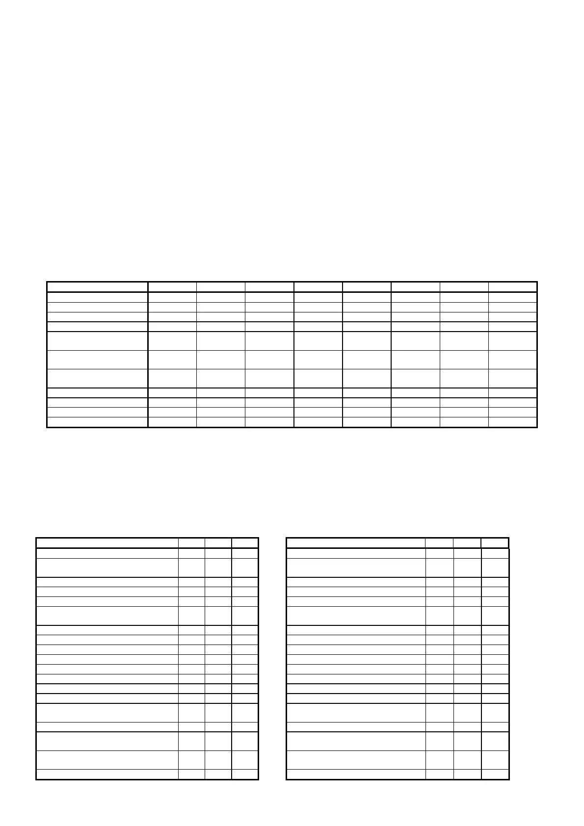
modify some of the unit's parameters, as listed below:
Parameter Unit Add. 1 Unit Add. 2 Unit Add. 3 Unit Add. 4 Unit Add. 5 Unit Add. 6 Unit Add. 7 Unit Add. 8
Temperature set point analogue 1 analogue 10 analogue 19 analogue 28 analogue 37 analogue 46 analogue 55 analogue 64
Humidity set point analogue 2 analogue 11 analogue 20 analogue 29 analogue 38 analogue 47 analogue 56 analogue 65
Recovery set point analogue 3 analogue 12 analogue 21 analogue 30 analogue 39 analogue 48 analogue 57 analogue 66
Compensation set point analogue 4 analogue 13 analogue 22 analogue 31 analogue 40 analogue 49 analogue 58 analogue 67
Low temperature alarm
threshold offset
analogue 5 analogue 14 analogue 23 analogue 32 analogue 41 analogue 50 analogue 59 analogue 68
High temperature alarm
threshold offset
analogue 6 analogue 15 analogue 24 analogue 33 analogue 42 analogue 51 analogue 60 analogue 69
Low humidity alarm
threshold offset
analogue 7 analogue 16 analogue 25 analogue 34 analogue 43 analogue 52 analogue 61 analogue 70
High humidity threshold offset analogue 8 analogue 17 analogue 26 analogue 35 analogue 44 analogue 53 analogue 62 analogue 71
Outlet air limit set point analogue 9 analogue 18 analogue 27 analogue 36 analogue 45 analogue 54 analogue 63 analogue 72
Unit On-off digital 1 digital 2 digital 3 digital 4 digital 5 digital 6 digital 7 digital 8
For details on the syntax of the SMS messages sent to the pCO* and on the use of the above table, refer to the manual: GSM modem protocol for
pCO2 (code+030220330).
N.B. When the GSM protocol is active, the remote supervisor cannot call the pCO1 or pCO2 board.
21.4 VARIABLE DATABASE
A specific communication database is featured that includes all the more important program variables, from the values read by the probes to the
parameters set on the screens. The following table describes the database, divided into digital, integer and analogue variables, indicating for
each its description, address and type, that is, read-only (R) or modifiable from the supervisor (R/W).
21.4.1 DIGITAL VARIABLES
DESCRIPTION SCR ADD TYPE DESCRIPTION SCR. ADD. TYPE
Digital input number 1 I3 1 R Humid. operating hour threshold alarm A36 63 R
Digital input number 2 I3 2 R Thermal cutout and high pressure alarm,
comp. 2
A37 64 R
Digital input number 3 I3 3 R Condens. 1 fan thermal cutout alarm A38 65 R
Digital input number 4 I3 4 R Condens. 2 fan thermal cutout alarm A39 66 R
Digital input number 5 I3 5 R Water flow alarm A40 67 R
Digital input number 6 I3 6 R Enable compressors/cooling coil together
with recovery coil
G0 69 R/W
Digital input number 7 I3 7 R Enable outside temperature probe Cl 70 R/W
Digital input number 8 I3 8 R Enable pressure probe 1 Ci 71 R/W
Digital input number 9 I3 9 R Enable pressure probe 2 Cj 72 R/W
Digital input number 10 I3 10 R Enable humidity probe Ch 73 R/W
Humidifier water level contact I3 11 R Enable outlet probe Ck 74 R/W
Digital input number 12 I3 12 R Enable condenser 1 temp. probe Cm 75 R/W
Digital input number 13 I3 13 R Enable condenser 2 temp. probe Cm 76 R/W
Digital input number 14 I3 14 R Enable recovery probe Cl 77 R/W
Digital output number 1 I7 15 R Modulating output 1 configuration
(0=rec. valve; 1=modulating fan)
Ca 78 R/W
Digital output number 2 I7 16 R Type of unit (0=ED; 1=CW) C1 79 R/W
Digital output number 3 I7 17 R Modulating output 2 configuration
(0=recovery valve; 1=humidifier)
Cb 80 R/W
Digital output number 4 I7 18 R Digital input 1 configuration
(0=fire/smoke; 1=flood)
C6 81 R/W
Digital output number 5 I7 19 R Di
ital in
ut 12 confi
uration C5 82 R/W
 Loading...


