17
INSTALLATION
Job-Site Survey
Complete the following checks before installation.
1. Consult local building codes and the NEC (National Elec-
trical Code) ANSI/NFPA 70 for special installation
requirements.
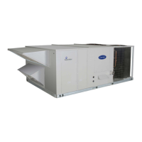
2. Determine unit location (from project plans) or select unit
location.
3. Check for possible overhead obstructions which may inter-
fere with unit lifting or rigging.
Step 1 — Plan for Unit Location
Select a location for the unit and its support system (curb or other)
that provides for the minimum clearances required for safety. This
includes the clearance to combustible surfaces, unit performance
and service access below, around and above unit as specified in
unit drawings. See Fig. 4, 8, and 12.
NOTE: Consider also the effect of adjacent units. Be sure that unit
is installed such that snow will not block the combustion intake or
flue outlet.
Unit may be installed directly on wood flooring or on class A, B,
or C roof-covering material when roof curb is used.
Do not install unit in an indoor location. Do not locate air inlets
near exhaust vents or other sources of contaminated air. For proper
unit operation, adequate combustion and ventilation air must be
provided in accordance with Section 5.3 (Air for Combustion and
Ventilation) of the National Fuel Gas Code, ANSI Z223.1 (Ameri-
can National Standards Institute) and NFPA (National Fire Protec-
tion Association) 54 TIA-54-84-1. In Canada, installation must be
in accordance with the CAN1-B149 installation codes for gas
burning appliances.
Although unit is weatherproof, avoid locations that permit water
from higher level runoff and overhangs to fall onto the unit.
Locate mechanical draft system flue assembly at least 4 ft (1.2 m)
from any opening through which combustion products could enter
the building, and at least 4 ft (1.2 m) from any adjacent building
(or per local code). Locate the flue assembly at least 10 ft (3.05 m)
from an adjacent unit’s fresh air intake hood if within 3 ft (0.91 m)
of same elevation (or per local code). When unit is located adja-
cent to public walkways, flue assembly must be at least 7 ft
(2.1 m) above grade.
Select a unit mounting system that provides adequate height to al-
low installation of condensate trap per requirements. Refer to
Step 10 — Install External Condensate Trap and Line – for re-
quired trap dimensions.
ROOF MOUNT
Check building codes for weight distribution requirements. Unit
operating weight is shown in Table 2.
Step 2 — Plan for Sequence of Unit Installation
The support method used for this unit will dictate different se-
quences for the steps of unit installation. For example, on curb-
mounted units, some accessories must be installed on the unit be-
fore the unit is placed on the curb. Review the following for rec-
ommended sequences for installation steps.
CURB-MOUNTED INSTALLATION
1. Install curb
2. Install field-fabricated ductwork inside curb
3. Install accessory thru-base service connection package
(affects curb and unit) (refer to accessory installation instruc-
tions for details)
4. Rig and place unit
5. Remove top skid
6. Install outdoor air hood
7. Install smoke detector tube
8. Install combustion air hood
9. Install flue hood
10. Install gas piping
11. Install condensate line trap and piping
12. Make electrical connections
13. Install other accessories
PAD-MOUNTED INSTALLATION
1. Prepare pad and unit supports
2. Rig and place unit
3. Remove duct covers and top skid
4. Install smoke detector return air sensor tube
5. Install field-fabricated ductwork at unit duct openings
6. Install outdoor air hood
7. Install combustion air hood
8. Install flue hood
9. Install gas piping
10. Install condensate line trap and piping
11. Make electrical connections
12. Install other accessories
FRAME-MOUNTED INSTALLATION
Frame-mounted applications generally follow the sequence for a
curb installation. Adapt as required to suit specific installation
plan.
Step 3 — Inspect Unit
Inspect unit for transportation damage. File any claim with trans-
portation agency. Confirm before installation of unit that voltage,
amperage and circuit protection requirements listed on unit data
plate agree with power supply provided.
On units with hinged panel option, check to be sure all latches are
tight and in closed position.
Locate the carton containing the outside air hood parts in the rear
blower assembly. Do not remove carton until unit has been rigged
and located in final position.
Step 4 — Provide Unit Support
ROOF CURB MOUNT
Assemble and install accessory roof curb in accordance with in-
structions shipped with the curb.
Curb should be level. This is necessary for unit drain to function
properly. Unit leveling tolerances are show in Fig. 14. Refer to Ac-
cessory Roof Curb Installation Instructions for additional informa-
tion as required.
Accessory roof curb details and dimensions are shown in
Fig. 16-18.
Install insulation, cant strips, roofing felt, and counter flashing as
shown. Ductwork must be attached to curb and not to the unit.
Thru-the-base power connection must be installed before the unit
is set on the roof curb. If field-installed thru-the-roof curb gas con-
nections are desired remove knockout in basepan located in the
gas section, see Fig. 15 for location. Gas connections and power
connections to the unit must be field installed after the unit is in-
stalled on the roof curb.
If electric and control wiring is to be routed through the basepan,
remove knockouts in basepan located in control box area, see
Fig. 15. Depending on the unit size, see Fig. 2, 6, or 10 for the lo-
cation of the knockouts. Attach the service connections to the
basepan.
 Loading...